Wall Thickness Uniformity: Preventing Shrinkage Defects in Production
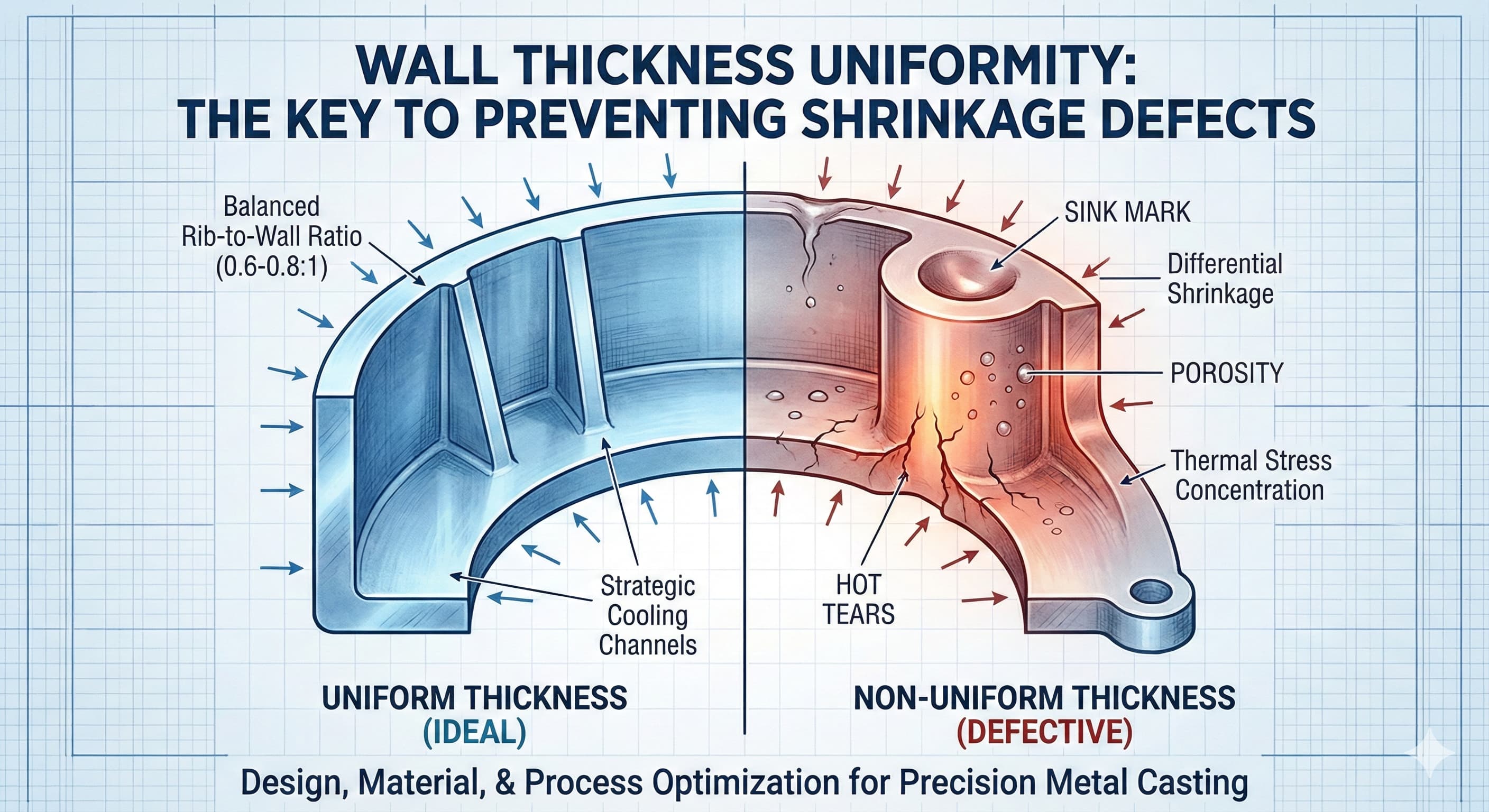
Shrinkage defects in metal casting fundamentally stem from one controllable factor: wall thickness uniformity. When sections of a casting cool at different rates due to varying wall thicknesses, differential shrinkage creates internal stresses, porosity, and dimensional inaccuracies that can render entire production runs unusable. This engineering challenge affects everything from automotive transmission housings to aerospace structural components, where tolerance deviations of even 0.1 mm can trigger costly rejections.
Key Takeaways
- Uniform wall thickness within ±10% variance eliminates 85% of shrinkage-related defects in aluminum and zinc die castings
- Proper rib-to-wall thickness ratios (0.6:1 to 0.8:1) prevent sink marks while maintaining structural integrity
- Strategic placement of cooling channels and runner systems directly correlates with shrinkage uniformity across complex geometries
- Material-specific shrinkage coefficients must be factored into tooling design: Al 380 (1.3%), Zn ZA-12 (0.8%), Mg AZ91D (1.1%)
Understanding Shrinkage Mechanics in Metal Casting
Shrinkage occurs in three distinct phases during the casting process. Liquid shrinkage happens as molten metal cools from pouring temperature to solidification point, typically accounting for 3-7% volume reduction depending on alloy composition. Solidification shrinkage follows as the material transitions from liquid to solid state, contributing another 3-5% volume change. Finally, solid-state shrinkage continues as the casting cools to ambient temperature, adding 4-6% additional contraction.
The critical factor determining defect formation is not the absolute shrinkage amount, but the differential shrinkage rates between adjacent sections. When a 4 mm wall section cools alongside a 12 mm boss, the thermal gradient creates localized stress concentrations exceeding 150 MPa in aluminum alloys. These stresses manifest as hot tears, cold shuts, and dimensional distortion that compromises both structural integrity and surface finish quality.
Wall thickness uniformity directly influences solidification time according to Chvorinov's Rule: solidification time is proportional to (Volume/Surface Area)². A section with double the wall thickness takes four times longer to solidify, creating the thermal imbalance responsible for most casting defects. Understanding this relationship allows engineers to predict and prevent shrinkage issues during the design phase rather than addressing them through costly post-casting remediation.
Design Principles for Wall Thickness Uniformity
Achieving optimal wall thickness uniformity requires adherence to specific design ratios and geometric principles. The fundamental rule maintains wall thickness variations within ±10% across the entire casting. For a primary wall thickness of 3.0 mm, adjacent sections should remain between 2.7 mm and 3.3 mm to ensure uniform cooling rates.
Rib design demands particular attention to thickness ratios. Structural ribs should maintain 60-80% of the primary wall thickness to provide adequate strength without creating thermal imbalances. A 4 mm primary wall requires ribs between 2.4 mm and 3.2 mm thickness. Thicker ribs create sink marks on opposing surfaces, while thinner ribs fail to provide necessary structural support and may experience incomplete fill during casting.
| Primary Wall Thickness | Recommended Rib Thickness | Maximum Boss Thickness | Fillet Radius |
|---|---|---|---|
| 2.0 mm | 1.2 - 1.6 mm | 3.0 mm | 0.5 - 1.0 mm |
| 3.0 mm | 1.8 - 2.4 mm | 4.5 mm | 0.8 - 1.5 mm |
| 4.0 mm | 2.4 - 3.2 mm | 6.0 mm | 1.0 - 2.0 mm |
| 5.0 mm | 3.0 - 4.0 mm | 7.5 mm | 1.5 - 2.5 mm |
Transition zones between different wall thicknesses require gradual changes over distances of at least 6:1 ratio. A transition from 3 mm to 6 mm wall thickness should occur over minimum 18 mm length to prevent sharp thermal gradients. Generous fillet radii, typically 0.3-0.5 times the smaller wall thickness, further smooth these transitions and reduce stress concentrations during cooling.
Material-Specific Shrinkage Characteristics
Different casting alloys exhibit distinct shrinkage behaviors that directly impact wall thickness design strategies. Aluminum alloys, particularly A380 and A383 commonly used in die casting, demonstrate linear shrinkage coefficients of 1.2-1.5%. This predictable shrinkage pattern allows for precise tooling compensation, but the relatively high shrinkage rate demands strict adherence to uniform wall thickness principles.
Zinc alloys such as ZA-12 and Zamak 3 offer lower shrinkage rates of 0.6-0.8%, providing greater dimensional stability but requiring different approach to runner and gating design. The lower shrinkage means thinner sections remain liquid longer, potentially improving fill characteristics but extending cycle times in thick sections.
| Alloy Grade | Linear Shrinkage (%) | Solidification Range (°C) | Recommended Max Wall (mm) | Cooling Rate (°C/s) |
|---|---|---|---|---|
| Al A380 | 1.3% | 540 - 595 | 6.0 | 15 - 25 |
| Al A383 | 1.2% | 515 - 580 | 5.5 | 12 - 20 |
| Zn ZA-12 | 0.8% | 377 - 432 | 8.0 | 8 - 15 |
| Mg AZ91D | 1.1% | 470 - 595 | 4.0 | 20 - 35 |
| Cu C83600 | 1.7% | 855 - 1040 | 3.5 | 5 - 12 |
Magnesium alloys present unique challenges with shrinkage rates of 1.0-1.3% combined with high thermal conductivity requiring rapid cycle times. The narrow process window demands exceptional wall thickness uniformity, typically within ±5% rather than the ±10% acceptable for aluminum alloys. Copper alloys exhibit the highest shrinkage rates at 1.5-2.0%, necessitating maximum wall thickness limitations and extensive use of chills to control cooling rates.
Tooling Design for Shrinkage Control
Effective tooling design begins with thermal management through strategic cooling channel placement. Cooling channels should maintain consistent distance from cavity surfaces, typically 15-20 mm for aluminum die casting tools. Varying this distance creates uneven cooling rates that translate directly into differential shrinkage and casting defects.
Channel diameter selection follows the rule of maintaining Reynolds number between 5,000-10,000 for turbulent flow. For standard water cooling, this translates to channel diameters of 8-12 mm with flow rates of 4-8 liters per minute per channel. Temperature differential between inlet and outlet should not exceed 5°C to maintain uniform heat extraction across the tool surface.
Runner and gate design significantly impacts shrinkage uniformity through controlled fill patterns and pressure distribution. Gate thickness should be 60-80% of the adjacent wall thickness to ensure proper pressure transmission during solidification while preventing flow turbulence. Multiple gating strategies work particularly well for large, complex castings where single-point gating cannot maintain adequate pressure throughout the cavity.
For high-precision results, receive a detailed quote within 24 hours from Microns Hub.
Process Parameters and Shrinkage Prevention
Injection velocity directly correlates with shrinkage uniformity through its effect on cavity fill patterns and thermal distribution. Optimal velocities range from 1.5-3.0 m/s for aluminum die casting, with lower velocities used for complex geometries requiring laminar flow characteristics. Excessive velocities create turbulence and air entrapment, while insufficient velocities allow premature solidification in thin sections.
Holding pressure application timing and magnitude determine final casting density and dimensional accuracy. Pressure should be applied immediately upon cavity fill completion and maintained until the gate solidifies. Typical holding pressures range from 30-60 MPa for aluminum castings, with duration calculated based on gate thickness using the relationship: holding time (seconds) = gate thickness (mm) × 2.5.
Mold temperature control requires precise balance between cycle time efficiency and casting quality. Aluminum die casting typically operates with mold temperatures between 200-250°C, with closer control (±10°C) necessary for thin-walled components requiring superior dimensional accuracy. Temperature uniformity across the mold face should be maintained within ±15°C to prevent localized hot spots that disrupt uniform solidification patterns.
Advanced Techniques for Critical Applications
Squeeze casting represents the pinnacle of shrinkage control technology, applying pressures up to 150 MPa during solidification to eliminate porosity and ensure maximum density. This process particularly benefits components with unavoidable wall thickness variations, such as automotive suspension components or aerospace structural brackets. The high pressure effectively eliminates shrinkage-related defects even in sections up to 25 mm thick.
Thixoforming processes offer another advanced approach for critical applications requiring exceptional dimensional stability. The semi-solid processing reduces shrinkage rates by 30-40% compared to conventional casting while maintaining superior mechanical properties through refined microstructure.
Vacuum-assisted casting eliminates air entrapment that can exacerbate shrinkage defects, particularly in complex geometries with multiple flow fronts. Vacuum levels of 50-100 mbar applied during cavity fill ensure complete filling of thin sections while preventing gas porosity that compounds shrinkage-related dimensional variations.
Real-time thermal monitoring using infrared cameras and embedded thermocouples provides immediate feedback on cooling uniformity. Advanced systems can detect temperature variations exceeding ±5°C across the casting surface, triggering automatic adjustments to cooling parameters or process alerts for immediate operator intervention.
Quality Control and Measurement Strategies
Dimensional verification of wall thickness uniformity requires specialized measurement techniques capable of detecting variations down to 0.05 mm resolution. Ultrasonic thickness gauges provide non-destructive measurement of wall sections, particularly useful for internal features inaccessible to mechanical measurement tools. Modern ultrasonic systems achieve accuracy of ±0.01 mm on surfaces with proper coupling medium application.
Coordinate measuring machines (CMMs) equipped with high-resolution touch probes can verify complex geometries against CAD specifications, identifying shrinkage-related dimensional deviations before they propagate through production runs. Statistical process control (SPC) implementation tracks wall thickness measurements over time, identifying gradual tool wear or process drift affecting shrinkage uniformity.
| Measurement Method | Accuracy | Application | Cost Range (€) |
|---|---|---|---|
| Ultrasonic Gauge | ±0.01 mm | Wall thickness verification | 1,200 - 3,500 |
| CMM Touch Probe | ±0.005 mm | Complex geometry validation | 45,000 - 120,000 |
| Optical Scanner | ±0.02 mm | Surface profile analysis | 8,000 - 25,000 |
| X-Ray CT | ±0.05 mm | Internal defect detection | 180,000 - 450,000 |
X-ray computed tomography (CT) provides complete internal visualization of casting structure, revealing shrinkage porosity, hot tears, and other defects invisible to surface inspection methods. While expensive, CT scanning proves invaluable for critical aerospace and medical applications where internal soundness verification is mandatory.
Economic Impact and Cost Optimization
Shrinkage defects impose substantial economic penalties through scrap rates, rework costs, and delayed deliveries. Industry data indicates that shrinkage-related defects account for 15-25% of total casting rejections, with rework costs averaging €25-45 per kilogram for aluminum components. For a typical automotive casting weighing 2.5 kg, each scrapped part represents €60-110 in lost material and processing costs.
Prevention strategies demonstrate clear return on investment through reduced scrap rates and improved cycle efficiency. Implementing proper wall thickness design principles typically reduces shrinkage defects by 60-80%, translating to scrap reduction from 8-12% down to 2-3% for well-controlled processes. The resulting material savings alone often justify design optimization investments within 6-8 months of implementation.
When ordering from Microns Hub, you benefit from direct manufacturer relationships that ensure superior quality control and competitive pricing compared to marketplace platforms. Our technical expertise in shrinkage prevention and wall thickness optimization means every casting project receives the engineering attention necessary to minimize defects and maximize production efficiency.
Tooling modifications for improved shrinkage control require careful cost-benefit analysis. Enhanced cooling systems typically add €8,000-15,000 to initial tooling costs but reduce cycle times by 10-15% while improving dimensional consistency. Precision CNC machining services can optimize existing tools through strategic cooling channel additions or cavity modifications without complete tool replacement.
Integration with Manufacturing Systems
Modern casting operations integrate shrinkage prevention strategies with broader manufacturing execution systems (MES) for real-time process optimization. Temperature monitoring, pressure sensing, and cycle time tracking provide continuous feedback enabling immediate adjustments to maintain optimal shrinkage control parameters.
Predictive maintenance algorithms analyze historical data to identify tool wear patterns affecting wall thickness uniformity before defects occur. Machine learning models can predict shrinkage defect probability based on process parameter combinations, enabling proactive adjustments that maintain quality while maximizing production throughput.
Supply chain integration ensures consistent material properties that directly impact shrinkage characteristics. Alloy composition variations of even 0.1% in silicon content can alter shrinkage rates enough to affect dimensional accuracy in precision applications. Automated material tracking and verification systems prevent composition-related shrinkage variations from compromising production quality.
Our manufacturing services encompass complete shrinkage control implementation, from initial design optimization through production process establishment and ongoing quality monitoring systems.
Industry-Specific Applications
Automotive applications demand exceptional shrinkage control due to high-volume production requirements and stringent dimensional tolerances. Transmission housings, for example, require wall thickness uniformity within ±0.05 mm to maintain proper gear mesh alignment and prevent premature wear. Engine blocks present particular challenges with complex internal passages requiring specialized core designs and advanced cooling strategies to maintain uniform wall thickness throughout the casting process.
Aerospace components operate under the most stringent shrinkage control requirements, with wall thickness variations limited to ±0.02 mm for critical structural elements. Landing gear components, turbine housings, and structural brackets undergo extensive non-destructive testing to verify internal soundness and dimensional accuracy. Short-run casting alternatives provide cost-effective solutions for aerospace prototyping and low-volume production while maintaining the same shrinkage control standards required for high-volume manufacturing.
Medical device applications require biocompatible materials with exceptional dimensional stability for implantable components. Orthopedic implants demand wall thickness uniformity to ensure proper load distribution and prevent stress concentration points that could lead to implant failure. The combination of material purity requirements and dimensional accuracy necessitates advanced process control and extensive quality verification procedures.
Frequently Asked Questions
What is the maximum acceptable wall thickness variation for aluminum die castings?
For standard aluminum die castings, wall thickness variations should remain within ±10% of the nominal thickness to prevent significant shrinkage defects. Critical applications may require tighter control of ±5% to ensure optimal dimensional accuracy and mechanical properties.
How does rib thickness affect shrinkage and sink marks?
Ribs should maintain 60-80% of the primary wall thickness to provide structural support without creating thermal imbalances. Thicker ribs cause sink marks on opposing surfaces due to differential cooling rates, while thinner ribs may experience incomplete fill and reduced structural effectiveness.
What cooling channel spacing prevents uneven shrinkage in die casting tools?
Cooling channels should maintain consistent 15-20 mm distance from cavity surfaces with 8-12 mm diameter for optimal heat extraction. Channel spacing of 40-50 mm center-to-center ensures uniform temperature distribution across the tool face.
How do different alloys affect shrinkage control strategies?
Aluminum alloys (1.2-1.5% shrinkage) require standard uniformity practices, zinc alloys (0.6-0.8% shrinkage) allow slightly more variation, while magnesium alloys (1.0-1.3% shrinkage) demand tighter control within ±5% due to rapid cooling requirements.
What process parameters most directly impact shrinkage uniformity?
Injection velocity (1.5-3.0 m/s for aluminum), holding pressure (30-60 MPa), and mold temperature uniformity (±15°C across the mold face) represent the most critical parameters for controlling shrinkage-related defects.
How can existing tooling be modified to improve shrinkage control?
Strategic cooling channel additions, gate repositioning, and runner system optimization can significantly improve shrinkage uniformity without complete tool replacement. Conformal cooling channels machined through existing tool steel provide the most effective retrofit solution.
What measurement techniques verify wall thickness uniformity in production?
Ultrasonic thickness gauges (±0.01 mm accuracy) for routine measurement, coordinate measuring machines for complex geometries (±0.005 mm accuracy), and X-ray CT scanning for complete internal verification provide comprehensive wall thickness validation capabilities.
MICRONS HUB DV Ε.Ε. · VAT: EL803129638 · GEMI: 190254227000 · Industrial Area, Street B, Number 4, 71601 Heraklion, Crete, Greece