V-Grooving: Creating Sharp Bends in Architectural Sheet Metal
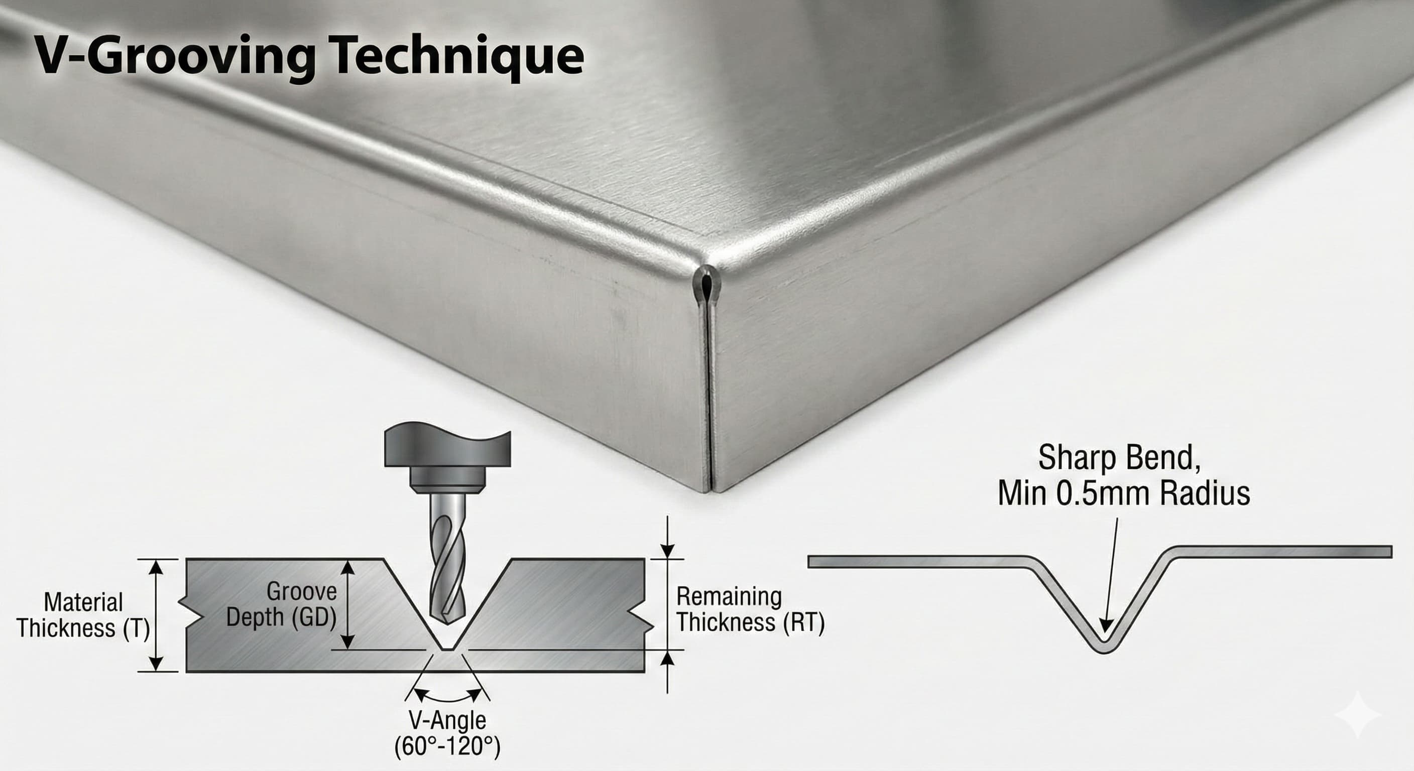
Sharp, precise bends in architectural sheet metal require more than standard brake forming—they demand V-grooving, a specialized technique that removes material along predetermined lines to create clean, accurate folds. This process enables bend radii as tight as 0.5 mm while maintaining structural integrity across materials from Al 6061-T6 to high-strength stainless steel grades.
Key Takeaways
- V-grooving achieves bend radii 60-80% smaller than conventional brake forming while eliminating material stress concentrations
- Groove depth calculations must account for material thickness, bend angle, and spring-back characteristics specific to each alloy
- Proper tool geometry and feed rates prevent work hardening and surface defects in architectural-grade finishes
- Cost-effectiveness emerges in medium to high-volume production runs where precision justifies the additional processing step
V-Grooving Fundamentals and Material Behavior
V-grooving creates a controlled weakness along the bend line by removing a triangular section of material from the outer surface. Unlike scoring or perforating, this process maintains material continuity while enabling sharp bends that would otherwise crack or wrinkle. The groove geometry follows specific mathematical relationships based on material properties and desired bend angles.
The critical depth calculation for V-grooves follows the formula: Groove Depth = (Material Thickness - Desired Remaining Thickness) where the remaining thickness typically ranges from 0.15 mm to 0.30 mm depending on material grade and application requirements. For Al 6061-T6 at 2.0 mm thickness targeting a 90-degree bend, optimal groove depth reaches 1.7 mm, leaving 0.3 mm of material to form the hinge.
Material selection significantly impacts V-grooving success rates. Aluminum alloys demonstrate excellent V-grooving characteristics, with 6061-T6 offering superior formability compared to 7075-T6's higher strength but reduced ductility. Understanding aluminum alloy behavior during bending operations becomes crucial for preventing micro-cracking along the groove edges.
| Material Grade | Max Groove Depth (%) | Min Bend Radius (mm) | Spring-back Factor | Cost Index (€/kg) |
|---|---|---|---|---|
| Al 6061-T6 | 85% | 0.5 | 1.02 | €4.20 |
| Al 5052-H32 | 80% | 0.7 | 1.04 | €4.50 |
| SS 316L | 75% | 1.2 | 1.15 | €8.90 |
| SS 304 | 78% | 1.0 | 1.12 | €7.60 |
| Mild Steel | 82% | 0.8 | 1.08 | €2.10 |
Tooling and Equipment Specifications
V-grooving requires specialized tooling designed to create consistent groove profiles while maintaining surface finish integrity. Router-based systems using carbide-tipped bits represent the most common approach for architectural applications, offering superior control over groove geometry compared to laser or waterjet alternatives.
Tool geometry specifications directly impact result quality. V-groove router bits feature included angles typically ranging from 60 to 120 degrees, with 90-degree tools providing optimal balance between material removal efficiency and structural strength retention. Cutting edge geometry incorporates specific relief angles—typically 12-15 degrees primary relief with 3-5 degrees secondary relief—to minimize cutting forces and prevent work hardening.
Feed rates and spindle speeds require careful optimization based on material properties. For aluminum alloys, optimal parameters include spindle speeds of 18,000-24,000 RPM with feed rates of 2.5-4.0 m/min. Stainless steel grades demand reduced speeds (12,000-16,000 RPM) with proportionally slower feed rates (1.5-2.5 m/min) to prevent excessive heat generation that could alter material microstructure.
Modern precision CNC machining services incorporate adaptive feed control systems that automatically adjust cutting parameters based on real-time force feedback, ensuring consistent groove quality across varying material thickness and hardness zones.
Process Parameters and Quality Control
Successful V-grooving depends on precise control of multiple interdependent variables. Groove depth tolerance typically maintains ±0.05 mm across the entire bend line length, requiring continuous monitoring through contact or non-contact measurement systems. Deviation beyond these limits results in inconsistent bend angles or potential material failure during forming.
Surface roughness within the groove significantly affects final part aesthetics and corrosion resistance. Architectural applications typically specify Ra values below 1.6 μm along groove surfaces, achievable through proper tool selection and cutting fluid application. Synthetic cutting fluids with extreme pressure additives prevent built-up edge formation while maintaining excellent surface finish.
For high-precision results, receive a detailed quote within 24 hours from Microns Hub.
Groove profile consistency across production runs requires statistical process control implementation. Critical control points include groove depth variation, sidewall angle consistency, and surface roughness measurements taken at predetermined intervals. Control charts tracking these parameters enable proactive tool maintenance and parameter adjustment before quality degradation occurs.
Temperature Management During Processing
Heat generation during V-grooving operations can significantly impact material properties and dimensional accuracy. Excessive temperatures promote grain boundary migration in aluminum alloys, potentially reducing fatigue resistance along the bend line. Temperature monitoring using infrared sensors ensures processing temperatures remain below critical thresholds—typically 150°C for aluminum alloys and 200°C for stainless steel grades.
Cooling strategies extend beyond conventional flood coolant application. Cryogenic cooling systems using liquid nitrogen or carbon dioxide provide superior temperature control while eliminating coolant-related contamination concerns critical in architectural applications requiring pristine surface finishes.
Forming Operations and Bend Accuracy
The forming operation following V-grooving requires specialized techniques to achieve the sharp bends that justify the additional processing cost. Standard press brake tooling proves inadequate for V-grooved parts, necessitating custom punch and die designs that accommodate the reduced material thickness along bend lines.
Bend angle accuracy depends heavily on spring-back compensation calculations specific to each material and groove configuration. Spring-back factors vary significantly between material grades, ranging from minimal correction (1-2 degrees) for work-hardened aluminum alloys to substantial compensation (8-12 degrees) for high-strength stainless steel grades.
Custom forming dies incorporate relief features that prevent interference with the V-groove geometry during the bending operation. These dies feature reduced contact area along the groove line while maintaining full support for the surrounding material, preventing localized deformation that could compromise bend quality.
| Bend Angle | Al 6061-T6 Spring-back | SS 316L Spring-back | Required Over-bend | Tolerance Achievement |
|---|---|---|---|---|
| 90° | 1.5° | 8.2° | 91.5° / 98.2° | ±0.5° |
| 120° | 2.1° | 11.4° | 122.1° / 131.4° | ±0.8° |
| 135° | 2.8° | 14.1° | 137.8° / 149.1° | ±1.0° |
| 150° | 3.2° | 16.8° | 153.2° / 166.8° | ±1.2° |
Cost Analysis and Economic Considerations
V-grooving economics depend on several factors including material costs, processing time, tooling requirements, and quality specifications. The additional processing step typically adds €0.15-0.35 per linear meter of groove, varying with material thickness and required precision levels.
Break-even analysis reveals V-grooving cost-effectiveness emerges around 50-75 pieces for typical architectural components. Below this threshold, alternative techniques such as laser cutting with micro-joints may prove more economical. Above 200 pieces, V-grooving demonstrates clear cost advantages while delivering superior aesthetic results.
Tool life considerations significantly impact per-part costs. Carbide router bits typically achieve 2,500-4,000 linear meters of grooving in aluminum alloys before requiring replacement, while stainless steel applications reduce tool life to 800-1,200 linear meters. Diamond-coated tooling extends service life by 3-4x but increases initial tooling costs by €200-300 per tool.
Surface Finishing Integration
V-grooving operations must consider downstream finishing processes to optimize total production costs. Powder coating applications require specific tolerance considerations as coating thickness varies between groove areas and flat surfaces.
Anodizing processes present unique challenges for V-grooved aluminum components. The reduced material thickness along groove lines creates current density variations during anodizing, potentially resulting in color variations. Specialized anodizing fixtures and current distribution systems address these challenges but add €0.25-0.45 per part in processing costs.
Quality Assurance and Inspection Protocols
Comprehensive quality assurance for V-grooved components extends beyond dimensional verification to include material integrity assessment and fatigue resistance evaluation. Visual inspection protocols identify potential defects including micro-cracking, tool marks, and surface contamination that could compromise long-term performance.
Dimensional inspection utilizes coordinate measuring machines (CMM) equipped with specialized software for groove profile analysis. Critical measurements include groove depth consistency, sidewall angle verification, and bend angle accuracy following forming operations. Statistical sampling plans based on MIL-STD-105E provide appropriate inspection frequencies while maintaining cost control.
When ordering from Microns Hub, you benefit from direct manufacturer relationships that ensure superior quality control and competitive pricing compared to marketplace platforms. Our technical expertise and integrated our manufacturing services approach means every V-grooving project receives the attention to detail it deserves, from initial design consultation through final quality verification.
Non-destructive testing methods verify material integrity along groove lines without compromising part functionality. Dye penetrant inspection reveals surface-breaking defects, while eddy current testing identifies subsurface flaws that could propagate during service loading. These testing protocols prove particularly critical for structural architectural applications where failure consequences justify the additional inspection costs.
Fatigue Performance Considerations
V-grooved bends introduce stress concentration factors that must be evaluated for cyclically loaded applications. Finite element analysis (FEA) modeling predicts fatigue life based on groove geometry, material properties, and anticipated loading conditions. Stress concentration factors typically range from 1.8-2.4 depending on groove depth and radius specifications.
Fatigue testing protocols following ASTM D7791 standards validate analytical predictions through controlled laboratory testing. Sample components undergo cyclic loading at stress levels representing 150% of anticipated service conditions, with failure criteria defined as visible crack propagation beyond the groove boundaries.
Design Guidelines and Best Practices
Effective V-groove design requires careful consideration of geometric relationships, material constraints, and manufacturing limitations. Design guidelines prevent common pitfalls while optimizing manufacturability and performance characteristics.
Minimum distance specifications between adjacent grooves prevent material weakening that could compromise structural integrity. For aluminum alloys, minimum spacing equals 5x material thickness, while stainless steel grades require 6x material thickness due to higher work hardening characteristics. Closer spacing necessitates finite element analysis to verify adequate strength margins.
Groove termination details significantly impact both aesthetics and structural performance. Tapered terminations extending 2-3 mm beyond the required bend line prevent stress concentrations while maintaining clean visual appearance. Abrupt groove terminations create stress risers that can initiate crack propagation under cyclic loading conditions.
| Design Parameter | Aluminum Alloys | Stainless Steel | Mild Steel | Impact on Cost |
|---|---|---|---|---|
| Min Groove Spacing | 5x thickness | 6x thickness | 4x thickness | High density = +15% |
| Max Groove Length | 3000 mm | 2500 mm | 3500 mm | Length >2m = +8% |
| Termination Taper | 2.5 mm | 3.0 mm | 2.0 mm | Standard feature |
| Surface Roughness | Ra 1.6 μm | Ra 1.2 μm | Ra 2.0 μm | Ra <1.0 = +25% |
Advanced Applications and Emerging Techniques
Emerging V-grooving applications push traditional boundaries through innovative approaches and advanced tooling systems. Multi-axis CNC machines enable compound groove geometries that create complex three-dimensional forms impossible through conventional techniques.
Laser-assisted V-grooving represents a hybrid approach combining thermal and mechanical material removal mechanisms. Pre-heating the material immediately ahead of the cutting tool reduces cutting forces by 30-40% while enabling deeper grooves in high-strength materials previously considered unsuitable for conventional V-grooving.
Adaptive control systems incorporating real-time force and temperature feedback optimize cutting parameters continuously throughout the grooving operation. Machine learning algorithms analyze historical data to predict optimal parameter combinations based on material batch variations and tool wear conditions, improving consistency while reducing operator skill requirements.
Integration with Digital Manufacturing
Digital twin technology enables virtual optimization of V-grooving parameters before physical production begins. Comprehensive models incorporating material properties, tool geometry, and machine dynamics predict optimal cutting conditions while identifying potential quality issues before they occur in production.
Automated inspection systems using machine vision technology provide 100% dimensional verification of groove geometry without impacting production throughput. High-resolution cameras combined with structured light projection create detailed 3D profiles of each groove, comparing results against CAD specifications with resolution capabilities below 0.01 mm.
Troubleshooting Common Defects
Systematic defect analysis and correction procedures ensure consistent V-grooving quality across varying production conditions. Understanding root causes enables rapid problem resolution while preventing recurring quality issues.
Chatter marks along groove surfaces typically result from insufficient machine rigidity or inappropriate cutting parameters. Solutions include reducing feed rates by 20-30%, increasing spindle speed within recommended ranges, or implementing vibration damping fixtures. Severe chatter may require machine dynamic analysis to identify resonant frequencies.
Groove depth variation exceeding ±0.05 mm often indicates tool wear, machine backlash, or workpiece deflection issues. Systematic measurement of groove depth at regular intervals identifies trending patterns that enable predictive tool replacement before quality degradation occurs. Workpiece fixturing must provide adequate rigidity to prevent deflection under cutting forces.
Material-Specific Challenges
Work hardening in stainless steel grades creates progressive tool wear and surface quality degradation. Mitigation strategies include optimized cutting fluid application, reduced cutting speeds, and specialized tool coatings designed for stainless steel applications. TiAlN coatings demonstrate superior performance compared to standard TiN alternatives.
Built-up edge formation on cutting tools degrades surface finish while creating dimensional inaccuracies. This phenomenon proves most problematic with aluminum alloys containing high silicon content. Sharp cutting edges, appropriate cutting speeds, and effective chip evacuation prevent built-up edge formation while extending tool life.
Frequently Asked Questions
What is the minimum material thickness suitable for V-grooving?
V-grooving works effectively on materials as thin as 0.8 mm, though optimal results occur with thicknesses of 1.5 mm and above. Thinner materials require specialized tooling and may achieve limited bend angles due to structural constraints along the groove line.
How does V-grooving affect material strength compared to standard bending?
V-grooving reduces cross-sectional area along the bend line, typically decreasing local strength by 15-25% depending on groove depth. However, the elimination of work hardening and residual stresses often results in superior fatigue performance compared to conventional bending methods.
Can V-grooved parts be welded or joined to other components?
Yes, V-grooved components accept standard joining methods including welding, brazing, and mechanical fastening. Welding requires careful heat management to prevent distortion along the thin groove areas. TIG welding with reduced amperage settings typically provides optimal results.
What tolerances are achievable for bend angles in V-grooved parts?
Bend angle tolerances of ±0.5° are routinely achievable for angles up to 90°, with ±1.0° typical for sharper bends up to 150°. Tighter tolerances require secondary operations or specialized forming techniques that increase processing costs by 20-30%.
How does surface finish in the groove affect final part appearance?
Groove surface finish directly impacts the final bend line appearance, particularly in brushed or polished finishes. Ra values below 1.6 μm ensure the groove area blends seamlessly with surrounding surfaces after forming, while rougher finishes may remain visible as a distinct line.
Is V-grooving suitable for outdoor architectural applications?
V-grooving proves excellent for outdoor applications when properly designed and finished. The reduced material thickness along bend lines requires consideration during corrosion protection planning, but properly anodized aluminum or passivated stainless steel components demonstrate equivalent durability to conventionally formed parts.
What are the typical lead times for V-grooved architectural components?
Lead times depend on complexity and quantity but typically range from 5-10 working days for standard architectural panels. Custom tooling requirements may add 3-5 days to initial orders, while repeat orders using existing tooling maintain standard lead times.
MICRONS HUB DV Ε.Ε. · VAT: EL803129638 · GEMI: 190254227000 · Industrial Area, Street B, Number 4, 71601 Heraklion, Crete, Greece