Minimum Bend Radii: Avoiding Cracks in Aluminum 5052 vs. 6061
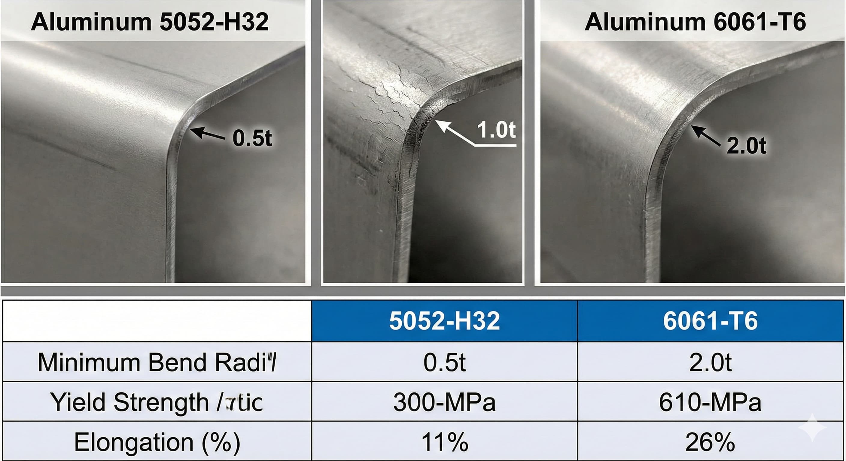
Aluminum bending failures cost European manufacturers millions annually, with 5052 and 6061 alloys representing over 70% of sheet metal applications. The critical difference lies in minimum bend radius requirements: 5052-H32 tolerates bending to 0.5t (material thickness), while 6061-T6 demands 2.0t minimum to prevent micro-cracking.
- Material Selection Impact: Al 5052-H32 offers superior formability with bend radii as tight as 0.5t, while Al 6061-T6 requires minimum 2.0t radius to avoid stress fractures
- Temper State Critical: Annealed conditions (O-temper) reduce minimum bend radius by 40-60% compared to work-hardened or precipitation-hardened states
- Grain Direction Matters: Bending parallel to rolling direction increases minimum bend radius by 25-30% due to grain structure alignment
- Cost-Quality Balance: Proper bend radius specification prevents 95% of cracking failures while maintaining dimensional accuracy within ±0.1 mm
Understanding Aluminum Alloy Fundamentals for Bending Applications
The fundamental difference between aluminum 5052 and 6061 lies in their metallurgical composition and strengthening mechanisms. Al 5052 belongs to the 5xxx series, strengthened through magnesium additions (2.2-2.8%) and work hardening. This creates a face-centered cubic crystal structure that maintains excellent ductility even after cold working.
Al 6061 represents the 6xxx series, utilizing magnesium (0.8-1.2%) and silicon (0.4-0.8%) for precipitation hardening through heat treatment. The T6 temper achieves peak strength through controlled aging, but sacrifices formability. This trade-off directly impacts minimum bend radius requirements.
When specifying materials for sheet metal fabrication services, understanding these metallurgical differences prevents costly redesigns. The work-hardening coefficient (n-value) for 5052-H32 typically ranges 0.20-0.25, while 6061-T6 measures only 0.05-0.08, indicating significantly reduced strain-hardening capacity.
| Property | Al 5052-H32 | Al 6061-T6 | Impact on Bending |
|---|---|---|---|
| Yield Strength (MPa) | 193-228 | 276-310 | Higher strength = larger bend radius |
| Elongation (%) | 12-18 | 8-12 | Lower ductility = cracking risk |
| Work Hardening Exponent | 0.20-0.25 | 0.05-0.08 | Low n-value = poor formability |
| Minimum Bend Radius | 0.5t-1.0t | 2.0t-3.0t | Critical for crack prevention |
Minimum Bend Radius Calculations and Standards
Calculating minimum bend radius requires understanding the relationship between material properties, sheet thickness, and stress distribution. The basic formula considers tensile strength, elongation, and a safety factor specific to each alloy system.
For Al 5052-H32, the minimum bend radius calculation follows: R_min = t × (UTS/2σ_y - 1), where UTS represents ultimate tensile strength and σ_y indicates yield strength. This typically yields 0.5t to 1.0t for most sheet thicknesses from 0.5 mm to 6.0 mm.
Al 6061-T6 requires a modified approach due to its precipitation-hardened structure: R_min = t × [(UTS/1.5σ_y) + K], where K represents a material constant (1.5-2.0) accounting for reduced ductility. This calculation explains why 6061-T6 demands 2.0t to 3.0t minimum bend radius.
ISO 2768-2 provides general tolerances for bent sheet metal parts, but specifying minimum bend radius requires reference to ISO 12004-2 for cold-formed steel products principles, adapted for aluminum applications. European EN 485-2 standard specifically addresses aluminum sheet tolerances and forming requirements.
Thickness-Dependent Bend Radius Requirements
Material thickness directly influences minimum bend radius through stress concentration effects. Thicker materials experience higher stress gradients across the bend zone, requiring proportionally larger radii to distribute loads effectively.
| Thickness (mm) | Al 5052-H32 Min Radius | Al 6061-T6 Min Radius | Recommended Tooling |
|---|---|---|---|
| 0.5-1.0 | 0.5-1.0 mm | 1.0-3.0 mm | Sharp punch, 1-2 mm die radius |
| 1.0-2.0 | 0.8-2.0 mm | 2.0-6.0 mm | 2-3 mm punch radius |
| 2.0-4.0 | 1.5-4.0 mm | 4.0-12.0 mm | 4-6 mm tooling radius |
| 4.0-6.0 | 2.5-6.0 mm | 8.0-18.0 mm | 8-12 mm forming radius |
For high-precision results, Submit your project for a 24-hour quote from Microns Hub.
Grain Direction Effects on Bend Performance
Rolling direction significantly impacts bend radius requirements and crack formation tendencies. Aluminum sheets exhibit directional properties due to grain elongation during rolling processes, creating anisotropic behavior that affects formability.
Bending parallel to the rolling direction (with the grain) typically requires 25-30% larger minimum bend radius compared to perpendicular bending. This occurs because elongated grains create preferential crack propagation paths along grain boundaries when stressed parallel to their length.
For Al 5052-H32, bending perpendicular to rolling direction achieves 0.5t radius reliably, while parallel bending may require 0.8t minimum. Al 6061-T6 shows more pronounced directional effects: perpendicular bending allows 2.0t radius, while parallel orientation demands 2.5-3.0t minimum.
Material certificates should specify rolling direction, typically marked with arrows or grain flow indicators. When designing parts requiring tight bend radii, orient bends perpendicular to rolling direction wherever possible. This consideration integrates naturally with our manufacturing services planning process.
Metallurgical Structure Impact
The underlying crystal structure explains directional behavior differences between alloys. Al 5052's work-hardened structure contains relatively uniform dislocation networks that accommodate deformation more consistently across orientations.
Al 6061-T6's precipitate structure creates localized stress concentrations at Mg2Si particles. These precipitates align somewhat with rolling direction, creating anisotropic failure modes. Scanning electron microscopy reveals that cracks initiate at precipitate-matrix interfaces when bend radius falls below critical thresholds.
Understanding these microstructural effects enables optimization of part orientation during fabrication planning. Component designs should account for grain direction effects early in the development process to avoid manufacturing constraints.
Temper State Influence on Minimum Bend Radius
Temper designation profoundly affects bendability, with annealed (O-temper) conditions offering maximum formability at the expense of strength. The relationship between tempering and minimum bend radius follows predictable patterns based on dislocation density and precipitate distribution.
Al 5052 temper states range from fully annealed (5052-O) through various work-hardened conditions (H32, H34, H36). Each temper level increases strength while reducing ductility proportionally. 5052-O achieves bend radii as tight as 0.2t, while 5052-H38 (full hard) may require 1.5t minimum.
Al 6061 temper options include annealed (6061-O), solution heat treated (6061-T4), and precipitation hardened (6061-T6). The dramatic difference between T4 and T6 conditions illustrates aging effects: T4 permits 0.8-1.2t bend radius, while T6 demands 2.0-3.0t minimum.
| Alloy-Temper | Yield Strength (MPa) | Min Bend Radius | Typical Applications |
|---|---|---|---|
| 5052-O | 90-110 | 0.2t-0.4t | Deep drawing, complex forms |
| 5052-H32 | 193-228 | 0.5t-1.0t | General fabrication |
| 5052-H38 | 262-290 | 1.2t-1.8t | Structural applications |
| 6061-O | 55-75 | 0.3t-0.6t | Complex bending operations |
| 6061-T4 | 145-186 | 0.8t-1.5t | Moderate strength needs |
| 6061-T6 | 276-310 | 2.0t-3.0t | High strength applications |
Practical Bend Radius Testing and Validation
Laboratory testing provides definitive minimum bend radius values for specific material lots and processing conditions. The standard test method involves progressive radius reduction until crack initiation occurs, typically observed at 10× magnification.
Test specimens should represent actual production material, including thickness, temper, and surface condition. Sample orientation relative to rolling direction must match intended part geometry. Testing typically employs 90-degree bend angles with constant punch velocity (5-10 mm/min) to ensure consistent strain rates.
Visual inspection criteria define failure as surface cracks visible at 10× magnification or measurable thickness reduction exceeding 10%. More stringent applications may require dye penetrant testing or ultrasonic inspection to detect subsurface defects.
Production validation involves bend testing on actual parts or representative samples from each material lot. Statistical process control charts track minimum bend radius capability over time, identifying material lot variations or processing changes affecting formability.
Quality Control and Inspection Methods
Effective quality control combines pre-bend material verification with post-bend inspection protocols. Incoming material inspection should verify temper designation, surface quality, and thickness uniformity within specified tolerances.
Post-bend inspection encompasses visual examination, dimensional verification, and structural integrity assessment. Critical applications may require non-destructive testing such as liquid penetrant inspection or magnetic particle testing adapted for aluminum applications.
When working with precision requirements, proper edge condition specification becomes crucial for both safety and performance. Bent edges require careful attention to prevent stress concentrations that could initiate fatigue failures.
Documentation should record material certificates, test results, and inspection findings for traceability. This becomes particularly important for aerospace or medical applications requiring full material genealogy.
Tooling Design Considerations for Crack Prevention
Proper tooling design represents the primary control method for achieving minimum bend radius without cracking. Punch and die geometry directly influence stress distribution in the bend zone, making tooling selection critical for success.
Punch nose radius should match or slightly exceed the intended part bend radius. Sharp punches concentrate stress excessively, while oversized punch radii create springback problems. The optimal punch radius typically equals 1.0-1.2× the desired part radius for aluminum applications.
Die opening width affects material flow and stress patterns significantly. Narrow die openings restrict material movement, increasing tensile stress on the outer fiber. The general rule specifies die opening width = 8-12× material thickness for aluminum, depending on bend radius and material properties.
Die shoulder radius prevents stress concentration at contact points while allowing controlled material flow. Sharp die shoulders create pressure points that can initiate surface defects. Recommended die shoulder radius ranges from 1-2× material thickness for most aluminum bending applications.
| Tooling Parameter | Al 5052-H32 | Al 6061-T6 | Function |
|---|---|---|---|
| Punch Radius | 0.5t-1.2t | 2.0t-3.5t | Forms bend radius |
| Die Opening | 8t-10t | 10t-12t | Controls material flow |
| Die Shoulder Radius | 1t-2t | 2t-3t | Reduces stress concentration |
| Punch-Die Clearance | 1.1t-1.2t | 1.2t-1.3t | Prevents binding/galling |
Cost Analysis: Material Selection vs. Design Complexity
Economic optimization requires balancing material costs against manufacturing complexity and failure risks. Al 5052-H32 typically costs €2,80-3,20 per kg, while Al 6061-T6 ranges €3,50-4,10 per kg in European markets, reflecting different processing requirements.
However, total cost includes forming complexity factors. Parts requiring tight bend radii may necessitate annealed material with subsequent heat treatment, adding €150-250 per processing lot. Alternative approaches include design modifications to accommodate standard temper bend capabilities.
Failure costs significantly impact total project economics. Cracked parts require rework or scrapping, with replacement costs including material, labor, and schedule delays. Prevention through proper bend radius specification typically costs 5-10% of total part cost while eliminating 95% of bend-related failures.
When ordering from Microns Hub, you benefit from direct manufacturer relationships that ensure superior quality control and competitive pricing compared to marketplace platforms. Our technical expertise and personalized service approach means every project receives the metallurgical analysis and tooling optimization it deserves for crack-free results.
Return on Investment for Proper Design
Investing in proper bend radius analysis provides measurable returns through reduced scrap rates, improved cycle times, and enhanced part reliability. Manufacturing operations typically see 15-25% cost reductions when bend failures are eliminated through proper design.
Documentation and standardization of minimum bend radius requirements creates reusable knowledge that benefits future projects. Engineering teams can reference validated bend radius data rather than conducting expensive trial-and-error development cycles.
Long-term benefits include improved supplier relationships, reduced warranty claims, and enhanced product reliability. These factors contribute to competitive advantages that extend beyond immediate cost savings.
Advanced Applications and Special Considerations
Complex geometries require sophisticated analysis beyond basic minimum bend radius calculations. Multi-bend sequences, varying material thicknesses, and compound curves create stress interactions that affect crack formation tendencies.
Sequential bending operations can work-harden material locally, reducing formability for subsequent bends. This effect is particularly pronounced in Al 5052, where each forming operation increases local yield strength by 15-25%. Planning bend sequences requires consideration of cumulative strain hardening effects.
Compound curves involve simultaneous bending in multiple planes, creating complex stress states not captured by simple bend radius calculations. Finite element analysis becomes necessary for accurate prediction of forming limits in such applications.
Temperature effects modify material properties significantly. Warm forming (150-200°C) can reduce minimum bend radius by 30-50% for both alloys, but requires specialized equipment and process control. Cryogenic forming occasionally finds application for specific high-strength requirements.
Integration with other processes such as welding or machining creates additional considerations. Heat-affected zones from welding alter local material properties, potentially affecting bend performance near weld seams. Machined features can create stress concentrations that influence crack initiation tendencies.
Frequently Asked Questions
What is the absolute minimum bend radius for aluminum 5052-H32 without cracking?
Aluminum 5052-H32 can achieve bend radii as tight as 0.5t (half the material thickness) when bending perpendicular to the rolling direction with proper tooling. For parallel-to-grain bending, increase minimum radius to 0.8t. These values assume standard forming speeds, room temperature, and proper die design with adequate clearances.
Why does aluminum 6061-T6 require such large bend radii compared to 5052?
Al 6061-T6's precipitation-hardened structure contains Mg2Si particles that create localized stress concentrations and reduce overall ductility. The T6 temper achieves high strength through controlled aging, but this process significantly reduces the work-hardening coefficient from 0.20+ (in 5052) to only 0.05-0.08, requiring 2.0-3.0t minimum bend radius to prevent micro-cracking.
Can I reduce minimum bend radius by changing the temper condition?
Yes, significantly. Changing from 6061-T6 to 6061-T4 reduces minimum bend radius from 2.0-3.0t to 0.8-1.5t. For 5052, annealed condition (5052-O) permits 0.2-0.4t radius compared to 0.5-1.0t for H32 temper. However, strength properties decrease proportionally with improved formability.
How does rolling direction affect bend radius requirements?
Bending parallel to rolling direction typically increases minimum bend radius by 25-30% due to grain elongation effects. For critical applications, orient bends perpendicular to rolling direction when possible. Material certificates should indicate rolling direction with directional arrows or grain flow markings.
What tooling modifications help achieve tighter bend radii?
Optimize punch nose radius to match desired part radius (1.0-1.2× target radius), use appropriate die opening width (8-12× thickness), and ensure adequate die shoulder radius (1-3× thickness). Proper punch-die clearance (1.1-1.3× thickness) prevents galling while allowing controlled material flow during forming.
How can I test minimum bend radius for my specific material lot?
Perform progressive bend testing using representative samples with the same thickness, temper, and orientation as production parts. Reduce bend radius incrementally until surface cracks appear at 10× magnification. Test both parallel and perpendicular orientations to rolling direction for complete characterization.
What inspection methods detect bend-related defects most effectively?
Visual inspection at 10× magnification captures most surface defects. For critical applications, use liquid penetrant testing to reveal subsurface cracks. Ultrasonic testing can detect internal defects, while dimensional inspection verifies bend radius accuracy within specified tolerances. Establish statistical process control for ongoing quality monitoring.
MICRONS HUB DV Ε.Ε. · VAT: EL803129638 · GEMI: 190254227000 · Industrial Area, Street B, Number 4, 71601 Heraklion, Crete, Greece