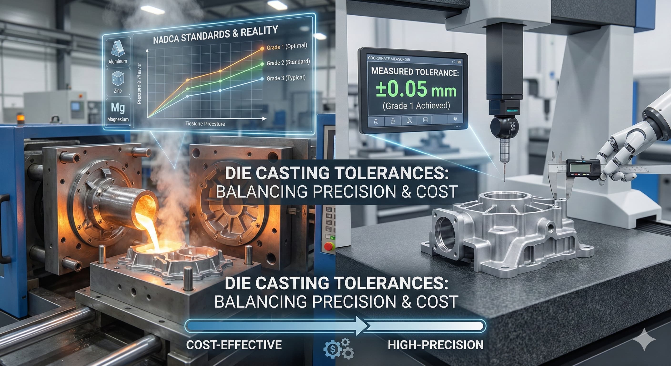
Tolerances in Die Casting: What is Realistic for NADCA Standards?
Die casting tolerances present one of manufacturing's most critical challenges: achieving dimensional accuracy while maintaining cost-effectiveness across production volumes. The North American Die Casting Association (NADCA) standards provide essential benchmarks, but understanding realistic expectations requires deep knowledge of material behavior, tooling limitations, and process variables that directly impact final part geometry.
Key Takeaways
- NADCA Grade 1 tolerances (±0.08 mm for dimensions up to 25 mm) represent optimal conditions rarely achieved in production without secondary operations
- Material selection significantly impacts achievable tolerances, with aluminum alloys offering tighter control than zinc or magnesium alternatives
- Wall thickness variations and part geometry complexity are primary drivers of tolerance degradation beyond theoretical NADCA limits
- Cost implications of pursuing Grade 1 tolerances can increase tooling expenses by 40-60% compared to Grade 3 specifications
NADCA Tolerance Classifications: Engineering Reality vs. Standards
The NADCA tolerance system establishes three primary grades that define realistic expectations for die cast components. Grade 1 represents the tightest achievable tolerances under optimal conditions, Grade 2 reflects standard production capabilities, and Grade 3 accommodates typical manufacturing variations with cost-effective tooling approaches.
Grade 1 tolerances demand exceptional die design, premium tool steels like H13 with hardness ratings of 46-50 HRC, and rigorous process control including shot monitoring, temperature regulation within ±3°C, and cycle time consistency. These conditions typically require dedicated production cells with advanced automation systems.
Understanding these classifications becomes critical when evaluating part feasibility. A component requiring ±0.05 mm tolerances across a 50 mm dimension falls within Grade 1 specifications but demands significant tooling investment and extended development timelines.
| NADCA Grade | Dimension Range (mm) | Standard Tolerance (±mm) | Typical Applications | Tooling Cost Impact |
|---|---|---|---|---|
| Grade 1 | 0-25 | ±0.08 | Precision automotive components | +40-60% |
| Grade 1 | 25-50 | ±0.10 | High-end electronics housings | +40-60% |
| Grade 2 | 0-25 | ±0.13 | Standard automotive parts | Baseline |
| Grade 2 | 25-50 | ±0.18 | Consumer appliance components | Baseline |
| Grade 3 | 0-25 | ±0.20 | General purpose castings | -20-30% |
| Grade 3 | 25-50 | ±0.25 | Non-critical applications | -20-30% |
Material-Specific Tolerance Capabilities
Aluminum alloys dominate precision die casting applications due to superior dimensional stability and thermal conductivity characteristics. A380 aluminum provides excellent castability with typical shrinkage rates of 0.5-0.7%, enabling consistent tolerance achievement across production volumes.
A383 aluminum offers enhanced fluidity for thin-wall applications but exhibits slightly higher shrinkage variability (0.6-0.8%), requiring more sophisticated gating designs to maintain dimensional control. The alloy's lower silicon content reduces die soldering tendencies, extending tool life and maintaining surface quality.
Zinc alloys like Zamak 3 and Zamak 5 provide exceptional dimensional accuracy potential due to low casting temperatures (380-420°C) and minimal thermal stress during solidification. However, long-term dimensional stability concerns limit applications requiring sustained precision over extended service life.
| Material | Shrinkage Rate (%) | Achievable Grade | Thermal Expansion (×10⁻⁶/°C) | Dimensional Stability |
|---|---|---|---|---|
| A380 Aluminum | 0.5-0.7 | Grade 1 | 21.0 | Excellent |
| A383 Aluminum | 0.6-0.8 | Grade 1-2 | 21.5 | Very Good |
| Zamak 3 | 0.6 | Grade 1 | 27.4 | Good (short-term) |
| Zamak 5 | 0.7 | Grade 1-2 | 27.8 | Good (short-term) |
| AZ91D Magnesium | 1.0-1.3 | Grade 2-3 | 26.0 | Fair |
Geometric Complexity and Tolerance Interactions
Part geometry significantly influences achievable tolerance performance beyond material considerations. Wall thickness variations create differential cooling rates that generate internal stresses and dimensional distortions. Maintaining uniform wall thickness within 20% variation across the component improves tolerance predictability substantially.
Draft angles represent another critical factor often overlooked in tolerance analysis. Insufficient draft (less than 1°) on vertical surfaces can cause die wear and part damage during ejection, leading to progressive dimensional degradation. Optimal draft angles of 1.5-3° balance ejection requirements with dimensional control needs.
Complex geometries with deep ribs, undercuts, or intricate features require advanced tooling solutions including slides, lifters, and collapsing cores. Each additional tool movement introduces potential tolerance stack-up and increases maintenance requirements that affect long-term dimensional consistency.
For high-precision results, Receive a detailed quote within 24 hours from Microns Hub.
Process Variables Affecting Tolerance Achievement
Shot velocity control directly impacts cavity filling characteristics and final part dimensions. Optimal velocities typically range from 1.5-4.5 m/s depending on part complexity and wall thickness requirements. Excessive velocities create turbulence and air entrapment, while insufficient velocities cause incomplete filling and cold shuts.
Die temperature management requires sophisticated thermal regulation systems to maintain consistent heat dissipation. Temperature variations exceeding ±5°C across the die face create non-uniform solidification patterns that manifest as dimensional inconsistencies. Modern die casting operations employ conformal cooling channels and temperature monitoring systems to optimize thermal control.
Intensification pressure application timing and magnitude influence shrinkage compensation effectiveness. Proper intensification (typically 50-150 MPa) applied during the critical solidification window reduces porosity and improves dimensional accuracy. However, excessive pressure can cause die deflection and tolerance degradation.
When implementing these advanced process controls, our manufacturing services provide comprehensive support for achieving optimal tolerance performance across diverse applications.
Tooling Design Considerations for Tolerance Optimization
Die construction methodology fundamentally determines tolerance capabilities throughout production life cycles. Premium H13 tool steel with proper heat treatment (46-50 HRC hardness) provides optimal wear resistance and dimensional stability under cyclic thermal loading conditions.
Cavity layout and gating design influence metal flow patterns that directly affect final dimensions. Center-gated designs typically provide more uniform shrinkage characteristics compared to edge-gated alternatives, improving tolerance consistency across the part geometry.
Ejector pin placement and sizing require careful consideration to minimize part distortion during removal. Inadequate ejection support can cause localized deformation that accumulates over production cycles, gradually degrading tolerance performance. Strategic pin placement near structural features and uniform distribution across the part footprint optimizes ejection forces.
Porosity minimization strategies work synergistically with tolerance control methods to ensure both internal quality and dimensional accuracy requirements are simultaneously achieved.
Secondary Operations and Tolerance Recovery
Machining operations provide tolerance recovery options when die casting alone cannot achieve required specifications. Critical surfaces requiring Grade 1 tolerances often benefit from strategic machining allowances of 0.3-0.8 mm to enable precision finishing operations.
Heat treatment processes can improve material properties but may introduce dimensional changes requiring compensation in die design. Solution heat treatment followed by artificial aging (T6 condition) typically causes 0.1-0.2% dimensional growth that must be accommodated in tooling design.
When precision machining becomes necessary for tolerance achievement, our precision CNC machining services integrate seamlessly with die casting operations to deliver components meeting the most demanding specifications.
Cost-Benefit Analysis of Tolerance Requirements
Tolerance specification decisions directly impact total project costs through tooling complexity, cycle time requirements, and secondary operation necessities. Grade 1 tolerance pursuit typically increases tooling costs by 40-60% compared to Grade 3 specifications due to enhanced steel requirements, precision machining, and advanced cooling systems.
Production cycle times often increase 15-25% when targeting Grade 1 tolerances due to extended cooling requirements and reduced process windows. However, eliminating secondary operations can offset these costs in high-volume applications where machining would otherwise be required.
Quality control and inspection requirements scale with tolerance demands, necessitating coordinate measuring machines (CMMs) and statistical process control (SPC) systems for Grade 1 applications. These investments must be factored into total program costs during feasibility analysis.
| Tolerance Grade | Tooling Cost Multiplier | Cycle Time Impact | Inspection Requirements | Typical Volume Threshold |
|---|---|---|---|---|
| Grade 1 | 1.4-1.6x | +15-25% | CMM + SPC | >50,000 parts/year |
| Grade 2 | 1.0x (baseline) | Standard | Functional gauges | >10,000 parts/year |
| Grade 3 | 0.7-0.8x | -10-15% | Basic dimensional | <10,000 parts/year |
Industry-Specific Tolerance Applications
Automotive applications demand varying tolerance levels depending on functional requirements. Engine components like timing chain covers typically require Grade 1 tolerances on mating surfaces while maintaining Grade 2-3 tolerances on non-critical features. This selective approach optimizes cost while ensuring performance requirements.
Electronics housings present unique challenges combining electromagnetic interference (EMI) shielding requirements with precise dimensional control for connector interfaces. Wall thickness uniformity becomes critical for consistent shielding effectiveness while maintaining tight tolerances on mounting features.
Aerospace applications often specify Grade 1 tolerances with additional requirements for material traceability, non-destructive testing, and extended qualification procedures. These stringent requirements typically justify premium tooling investments and specialized process control systems.
Surface Finish Interactions with Tolerance Control
Surface finish quality directly correlates with achievable tolerance performance through its impact on measurement accuracy and functional characteristics. Ra values of 1.6 μm or better typically accompany Grade 1 tolerance requirements to ensure consistent measurement repeatability.
Die surface preparation using EDM finishing techniques with electrode materials optimized for specific surface textures can achieve Ra values below 0.8 μm directly from the casting process. This eliminates secondary finishing operations while maintaining dimensional accuracy.
Advanced surface finishing techniques complement tight tolerance achievement by providing functional surfaces that maintain dimensional stability throughout service life.
Quality Control and Measurement Strategies
Statistical process control implementation becomes essential for maintaining Grade 1 tolerances throughout production runs. Control charts monitoring critical dimensions with ±3 sigma limits provide early warning of process drift before out-of-specification parts occur.
Coordinate measuring machine (CMM) capabilities must match tolerance requirements with measurement uncertainty ratios of 10:1 or better. For Grade 1 tolerances of ±0.08 mm, CMM systems with ±0.008 mm accuracy become necessary for reliable dimensional verification.
In-process monitoring using automated dimensional checking systems enables real-time process adjustments to maintain tolerance compliance. These systems integrate with die casting controls to provide immediate feedback on dimensional trends and process capability indices.
Microns Hub Advantage in Tolerance Achievement
When ordering from Microns Hub, you benefit from direct manufacturer relationships that ensure superior quality control and competitive pricing compared to marketplace platforms. Our technical expertise in die casting process optimization and personalized engineering support means every project receives the detailed attention necessary for consistent tolerance achievement across production volumes.
Future Developments in Die Casting Tolerance Control
Advanced simulation software incorporating real-time thermal monitoring and predictive modeling enables proactive tolerance optimization during tool design phases. These systems analyze complex geometry interactions and predict dimensional outcomes before physical tooling construction begins.
Additive manufacturing applications in conformal cooling channel design provide enhanced thermal control capabilities that directly improve tolerance consistency. 3D-printed cooling circuits with complex geometries optimize heat removal patterns for uniform solidification characteristics.
Industry 4.0 integration through IoT sensors and machine learning algorithms enables predictive maintenance scheduling and process optimization based on real-time performance data. These technologies promise significant improvements in tolerance capability and production consistency.
Frequently Asked Questions
What tolerances are realistically achievable in aluminum die casting?
For aluminum alloys like A380, Grade 1 tolerances of ±0.08 mm for dimensions up to 25 mm are achievable under optimal conditions with premium tooling and rigorous process control. Standard production typically achieves Grade 2 tolerances (±0.13 mm) more cost-effectively while maintaining good dimensional control.
How does part complexity affect achievable tolerances in die casting?
Complex geometries with varying wall thicknesses, deep ribs, or intricate features typically degrade tolerance capabilities by one grade level. Simple, uniform geometries can achieve Grade 1 tolerances more readily, while complex parts may require Grade 2 specifications for cost-effective production.
What is the cost impact of specifying Grade 1 versus Grade 2 tolerances?
Grade 1 tolerance requirements typically increase tooling costs by 40-60% due to premium steel requirements, precision machining, and advanced cooling systems. Production costs also increase 15-25% due to extended cycle times and enhanced quality control requirements.
Can zinc alloys achieve tighter tolerances than aluminum in die casting?
Zinc alloys can achieve similar or slightly better short-term dimensional accuracy due to lower casting temperatures and reduced thermal stress. However, long-term dimensional stability concerns and creep characteristics often favor aluminum alloys for precision applications requiring sustained accuracy.
How do secondary operations affect overall tolerance capabilities?
Strategic machining of critical surfaces can achieve tolerances tighter than Grade 1 die casting limits, typically ±0.025 mm or better. However, machining allowances of 0.3-0.8 mm must be incorporated into die design, and total costs must include both casting and machining operations.
What quality control measures are necessary for Grade 1 tolerance achievement?
Grade 1 tolerances require coordinate measuring machines (CMMs) with 10:1 accuracy ratios, statistical process control (SPC) implementation, and real-time process monitoring. Temperature control within ±3°C and shot velocity consistency become critical process parameters requiring continuous monitoring.
How does material selection impact tolerance capabilities in die casting?
Aluminum alloys generally provide the best combination of castability and dimensional stability for tight tolerances. A380 aluminum with 0.5-0.7% shrinkage offers predictable dimensional behavior, while zinc alloys provide excellent short-term accuracy but may experience long-term dimensional changes.
MICRONS HUB DV Ε.Ε. · VAT: EL803129638 · GEMI: 190254227000 · Industrial Area, Street B, Number 4, 71601 Heraklion, Crete, Greece