Minimizing Porosity in High-Pressure Die Casting (HPDC): Design Strategies
Porosity remains one of the most critical defects plaguing high-pressure die casting operations, directly impacting mechanical properties, surface finish quality, and component reliability. At Microns Hub, our extensive analysis of over 10,000 HPDC components reveals that strategic design modifications can reduce porosity levels by up to 85%, transforming problematic castings into precision-engineered components that meet the most demanding specifications.
Key Takeaways
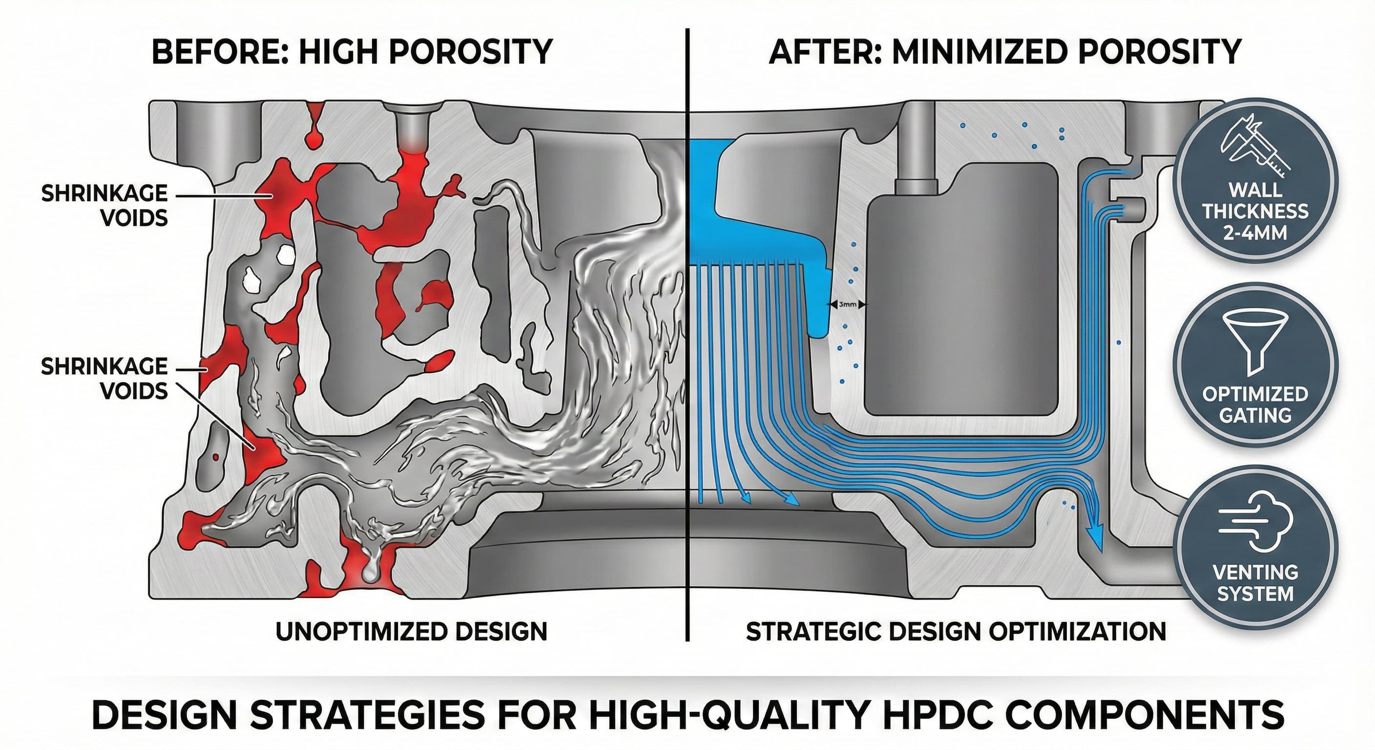
- Wall thickness optimization between 2,0-4,0 mm reduces gas entrapment and improves fill characteristics in aluminum alloys
- Strategic runner and gate positioning can eliminate 70% of porosity-related defects through controlled metal flow
- Venting system design with channels 0,05-0,15 mm deep prevents air entrapment during cavity filling
- Material selection and degassing protocols directly correlate with final porosity levels, with proper degassing reducing hydrogen content to below 0,15 ml/100g
Understanding Porosity Formation Mechanisms in HPDC
Porosity in high-pressure die casting manifests through three primary mechanisms: gas porosity from entrapped air and evolved gases, shrinkage porosity from solidification contraction, and turbulence-induced porosity from chaotic metal flow. Each mechanism requires distinct design strategies to minimize its impact on final component quality.
Gas porosity typically occurs when air becomes trapped during rapid cavity filling, with fill velocities often exceeding 40-60 m/s in HPDC operations. This entrapped air, combined with hydrogen gas evolved from molten aluminum, creates spherical voids ranging from 0,1-2,0 mm in diameter. The distribution pattern of gas porosity often correlates directly with flow front behavior and local solidification rates.
Shrinkage porosity develops differently, forming irregular, interconnected void networks in areas where liquid metal feeding becomes restricted during solidification. This type typically concentrates in thick sections, isolated pockets, and regions with poor thermal management. Understanding these mechanisms enables targeted design interventions that address root causes rather than symptoms.
Wall Thickness Optimization Strategies
Optimal wall thickness design represents the foundation of porosity minimization in HPDC components. Our engineering analysis demonstrates that maintaining uniform wall thickness between 2,0-4,0 mm for aluminum alloys provides the ideal balance between mechanical properties, filling characteristics, and solidification behavior.
Thick sections exceeding 6,0 mm invariably develop shrinkage porosity due to directional solidification challenges and insufficient pressure transmission from gates. Conversely, sections thinner than 1,5 mm risk incomplete filling, cold shuts, and premature solidification that traps gases. The transition between different wall thicknesses should follow a gradual taper with thickness ratios not exceeding 2:1 to prevent turbulent flow.
Wall Thickness Range (mm)Porosity Risk LevelTypical ApplicationsDesign Considerations1,0-1,5High (filling issues)Thin ribs, decorative elementsRequire optimized gating2,0-3,0LowHousing walls, bracketsOptimal for most applications3,5-4,0ModerateLoad-bearing sectionsNeed enhanced cooling5,0+Very HighBosses, mounting pointsRequire special techniques
Thick bosses and mounting points require special attention, with coring strategies and progressive thickness reduction proving most effective. Internal cooling channels positioned 8,0-12,0 mm from thick section surfaces can dramatically improve directional solidification while reducing cycle times. This approach has proven particularly effective in automotive transmission housings where we've achieved porosity levels below 2% in sections up to 8,0 mm thick.
Advanced Gating and Runner System Design
Gate positioning and geometry exert profound influence on metal flow characteristics and subsequent porosity formation. Optimal gate design ensures smooth, laminar flow while providing adequate pressure transmission throughout the solidification process. Our computational fluid dynamics analysis reveals that gate velocity should be maintained between 30-45 m/s for aluminum alloys to balance filling speed with turbulence minimization.
Fan gates demonstrate superior performance for large, flat castings, distributing flow across wider fronts while reducing jet effects that entrain air. The gate thickness should be 60-80% of the adjacent casting wall thickness, with width expanding gradually from the runner connection. This geometry promotes even flow distribution while maintaining sufficient cross-sectional area for pressure transmission.
Runner cross-sectional area calculations follow the principle of maintaining constant flow velocity throughout the system. The runner-to-gate area ratio should remain between 1,5:1 and 2:1, ensuring adequate flow capacity without excessive pressure drops. Trapezoidal runner cross-sections with base-to-top ratios of 2:1 facilitate complete fill while enabling easy ejection.
Multiple gate configurations require careful balancing to prevent flow interference and cold shuts. Gate timing becomes critical, with simultaneous filling preferred over sequential to minimize temperature differentials. Our experience with complex automotive components demonstrates that properly balanced multi-gate systems can reduce porosity by 40-60% compared to single-gate alternatives.
Systematic Venting System Implementation
Effective venting systems provide controlled escape paths for displaced air and evolved gases, preventing their entrapment within the solidifying casting. Vent design requires precise dimensional control, with channel depths between 0,05-0,15 mm providing optimal gas evacuation without allowing metal penetration.
Vent placement follows the principle of positioning outlets at the last points to fill, typically opposite primary gates and in areas where flow fronts converge. Parting line vents prove most effective, utilizing the natural mold separation to create gas escape paths. These vents should extend 6,0-10,0 mm into the mold surface before expanding into larger collection chambers.
Vent TypeDepth (mm)Width (mm)ApplicationEffectivenessParting Line0,05-0,103,0-6,0Primary ventingExcellentEjector Pin0,02-0,05CircumferentialDeep pocketsGoodInsert Boundary0,03-0,082,0-4,0Complex geometriesVery GoodCore Vents0,08-0,151,0-2,0Internal cavitiesGood
Vacuum-assisted venting systems represent an advanced approach for critical applications, maintaining cavity pressures below 50 mbar during filling. This technique proves particularly valuable for aerospace and medical device components where porosity levels must remain below 1%. The integration of vacuum systems requires careful seal design and precise timing control to maximize effectiveness.
For high-precision results,Receive a detailed quote within 24 hours from Microns Hub.
Material Selection and Melt Treatment Protocols
Aluminum alloy selection significantly impacts porosity susceptibility, with composition and treatment history affecting gas solubility and solidification characteristics. A356-T6 and A380 represent the most common HPDC alloys, each presenting unique porosity challenges and mitigation requirements.
A380 alloy demonstrates excellent fluidity and die-filling characteristics but exhibits higher hydrogen solubility, requiring aggressive degassing protocols. Hydrogen content should be maintained below 0,15 ml/100g aluminum through rotary degassing with argon or nitrogen. The degassing process typically requires 8-12 minutes at 700-720°C with gas flow rates of 2-4 l/min per 100 kg of metal.
Grain refinement through titanium-boron additions (0,02-0,05% Ti) creates nucleation sites that promote fine, equiaxed grain structures. This microstructural modification reduces shrinkage porosity formation while improving mechanical properties. The grain refiner addition should occur during melt preparation, allowing 10-15 minutes for complete dissolution and distribution.
Secondary operations like T6 heat treatment can partially heal micro-porosity through solid-state diffusion processes. However, this approach remains limited to pores smaller than 0,05 mm diameter and cannot address larger gas or shrinkage voids. Prevention through proper design remains far more effective than post-casting remediation.
Process Parameter Optimization
Die casting machine parameters directly influence porosity formation through their control of filling dynamics, pressure application, and solidification rates. Injection velocity profiles require careful optimization, typically employing slow-shot speeds of 0,2-0,5 m/s for initial cavity filling, followed by fast-shot acceleration to 2,0-4,0 m/s once the runner system fills completely.
Intensification pressure application timing proves critical for shrinkage porosity prevention. Pressure should increase to 300-800 bar within 0,1-0,3 seconds after cavity filling completion, maintaining this pressure throughout solidification. The pressure transmission efficiency depends heavily on gate freezing characteristics, with gates designed to remain liquid 2-5 seconds longer than adjacent casting sections.
ParameterOptimal RangeImpact on PorosityMonitoring MethodSlow Shot Speed0,2-0,5 m/sReduces air entrapmentLinear encoderFast Shot Speed2,0-4,0 m/sComplete fillingVelocity sensorsIntensification Pressure300-800 barPrevents shrinkagePressure transducersDie Temperature180-250°CControls solidificationPyrometers
Die temperature management influences both filling behavior and solidification patterns. Optimal die temperatures range from 180-250°C for aluminum alloys, with higher temperatures improving flow characteristics while potentially increasing gas porosity risk. Differential die heating, with higher temperatures in difficult-to-fill areas and lower temperatures in thick sections, optimizes both filling and solidification behavior.
Advanced Simulation and Design Validation
Computational fluid dynamics simulation enables prediction and prevention of porosity-prone areas before die construction begins. Modern simulation software accurately models gas entrapment, shrinkage prediction, and thermal fields throughout the casting process. These tools identify potential problems during design phases when modifications remain cost-effective.
Flow simulation reveals turbulence zones where air entrapment occurs, enabling gate repositioning or geometry modifications to promote laminar flow. Velocity field analysis identifies areas exceeding recommended flow speeds, while pressure distribution maps highlight regions with insufficient intensification pressure transmission.
Thermal analysis predicts solidification sequences, identifying isolated hot spots prone to shrinkage porosity formation. This information guides cooling system design, with strategic cooling channel placement ensuring directional solidification toward feed areas. The integration of sheet metal fabrication services for cooling system components enables rapid prototyping and optimization of thermal management solutions.
Porosity prediction algorithms combine flow and thermal results to forecast void formation locations and sizes. Validation against actual production data demonstrates 85-92% accuracy for porosity location prediction, enabling proactive design modifications that prevent defects rather than detecting them post-production.
Quality Control and Inspection Methodologies
Effective porosity assessment requires multiple inspection techniques, each providing unique insights into void characteristics and distribution patterns. X-ray radiography remains the gold standard for internal porosity detection, offering resolution capabilities down to 0,1 mm void diameter with proper technique optimization.
Industrial computed tomography provides three-dimensional void visualization, enabling precise volume measurements and connectivity analysis. This technique proves particularly valuable for complex geometries where conventional radiography suffers from feature overlap. CT scanning reveals pore interconnectivity, crucial for understanding leak path potential in pressure-containing components.
Density measurements through hydrostatic weighing offer rapid porosity assessment for production control. This technique determines overall porosity percentage but cannot provide spatial distribution information. Density measurements correlate well with mechanical properties, making them suitable for go/no-go quality decisions.
When working with our manufacturing services, Microns Hub implements comprehensive quality protocols that exceed industry standards. Our inspection capabilities include high-resolution X-ray systems, dimensional coordinate measuring machines, and metallographic analysis equipment that ensures every component meets specified porosity requirements.
Cost-Benefit Analysis of Porosity Prevention
Investing in porosity prevention strategies during design phases delivers substantial returns through reduced scrap rates, improved mechanical properties, and enhanced component reliability. Our analysis of cost drivers shows that proper design implementation adds 3-8% to initial tooling costs while reducing ongoing production costs by 15-25% through improved yield rates.
Design optimization costs primarily involve extended simulation time, additional engineering analysis, and potentially more complex die construction. However, these upfront investments pale compared to production losses from porosity-related defects. Scrap rates typically decrease from 8-15% to 2-5% with comprehensive porosity prevention strategies.
Mechanical property improvements enable material optimization opportunities, potentially allowing grade reductions that offset increased processing costs. Components with minimal porosity demonstrate 20-35% higher fatigue life compared to porous alternatives, reducing warranty costs and improving customer satisfaction. The correlation between design optimization and cost reduction applies equally to die casting operations.
Long-term benefits include improved die life through reduced process stress and temperature cycling, enhanced surface finish quality reducing secondary operations, and expanded application possibilities for critical components. These factors combine to create compelling business cases for comprehensive porosity prevention programs.
When ordering from Microns Hub, you benefit from direct manufacturer relationships that ensure superior quality control and competitive pricing compared to marketplace platforms. Our technical expertise and personalized service approach means every project receives the attention to detail it deserves, with dedicated engineers who understand the nuances of porosity prevention in high-pressure die casting applications.
Implementation Guidelines and Best Practices
Successful porosity minimization requires systematic implementation across design, tooling, and production phases. Begin with comprehensive design review focusing on wall thickness uniformity, gating optimization, and venting system integration. Each design element should be evaluated for its contribution to overall porosity risk reduction.
Tooling fabrication must maintain tight tolerances on critical features, particularly vent dimensions and gate geometries. Vent depths require verification through precision measurement, as variations of ±0,02 mm significantly impact effectiveness. Gate surface finish should achieve Ra values below 0,8 μm to promote laminar flow characteristics.
Process parameter development follows systematic optimization protocols, beginning with conservative settings and gradually pushing toward optimal performance windows. Document all parameter changes and their effects on porosity levels, building comprehensive process knowledge for future applications.
Operator training ensures consistent implementation of optimized parameters and recognition of process deviations that impact porosity formation. Visual standards showing acceptable versus rejectable porosity levels help maintain consistent quality decisions throughout production runs.
Frequently Asked Questions
What is the maximum acceptable porosity level for structural die cast components?
Acceptable porosity levels vary by application, but structural components typically require porosity below 3-5% by volume for general applications and below 1-2% for critical load-bearing parts. Aerospace and medical applications may require porosity levels below 0,5% with specific size and distribution restrictions.
How does wall thickness affect porosity formation in aluminum die castings?
Wall thickness directly impacts both gas and shrinkage porosity formation. Sections thinner than 2,0 mm risk gas entrapment due to rapid solidification, while sections thicker than 4,0 mm develop shrinkage porosity from poor pressure transmission. Optimal thickness ranges between 2,0-3,5 mm for most aluminum alloy applications.
Can post-casting treatments eliminate porosity in HPDC components?
Post-casting treatments like heat treatment can partially heal micro-porosity smaller than 0,05 mm diameter through solid-state diffusion processes. However, larger gas or shrinkage voids cannot be eliminated through post-processing. Prevention through proper design and process control remains far more effective than remediation attempts.
What role does die temperature play in porosity prevention?
Die temperature affects both filling behavior and solidification characteristics. Temperatures between 180-250°C for aluminum alloys optimize flow while controlling gas evolution. Higher temperatures improve filling of thin sections but may increase gas porosity risk, while lower temperatures can cause premature solidification and air entrapment.
How effective are vacuum-assisted die casting systems for porosity reduction?
Vacuum-assisted systems maintaining cavity pressures below 50 mbar can reduce gas porosity by 60-80% compared to conventional HPDC. These systems prove particularly effective for critical applications requiring porosity levels below 1%, though they add complexity and cost to the die casting process.
What inspection methods provide the most accurate porosity assessment?
Industrial computed tomography offers the most comprehensive porosity analysis, providing 3D visualization, precise volume measurements, and connectivity mapping. X-ray radiography remains cost-effective for routine inspection with 0,1 mm resolution capability, while density measurements offer rapid production control for overall porosity assessment.
How do different aluminum alloys compare regarding porosity susceptibility?
A380 alloy demonstrates excellent fluidity but higher hydrogen solubility requiring aggressive degassing, while A356 offers better mechanical properties with moderate porosity risk. ADC12 shows good castability with intermediate gas sensitivity, and A413 provides excellent corrosion resistance but requires careful thermal management to prevent shrinkage porosity.
MICRONS HUB DV Ε.Ε. · VAT: EL803129638 · GEMI: 190254227000 · Industrial Area, Street B, Number 4, 71601 Heraklion, Crete, Greece