Reducing Tool Wear in Titanium Machining: Optimized CAD Strategies
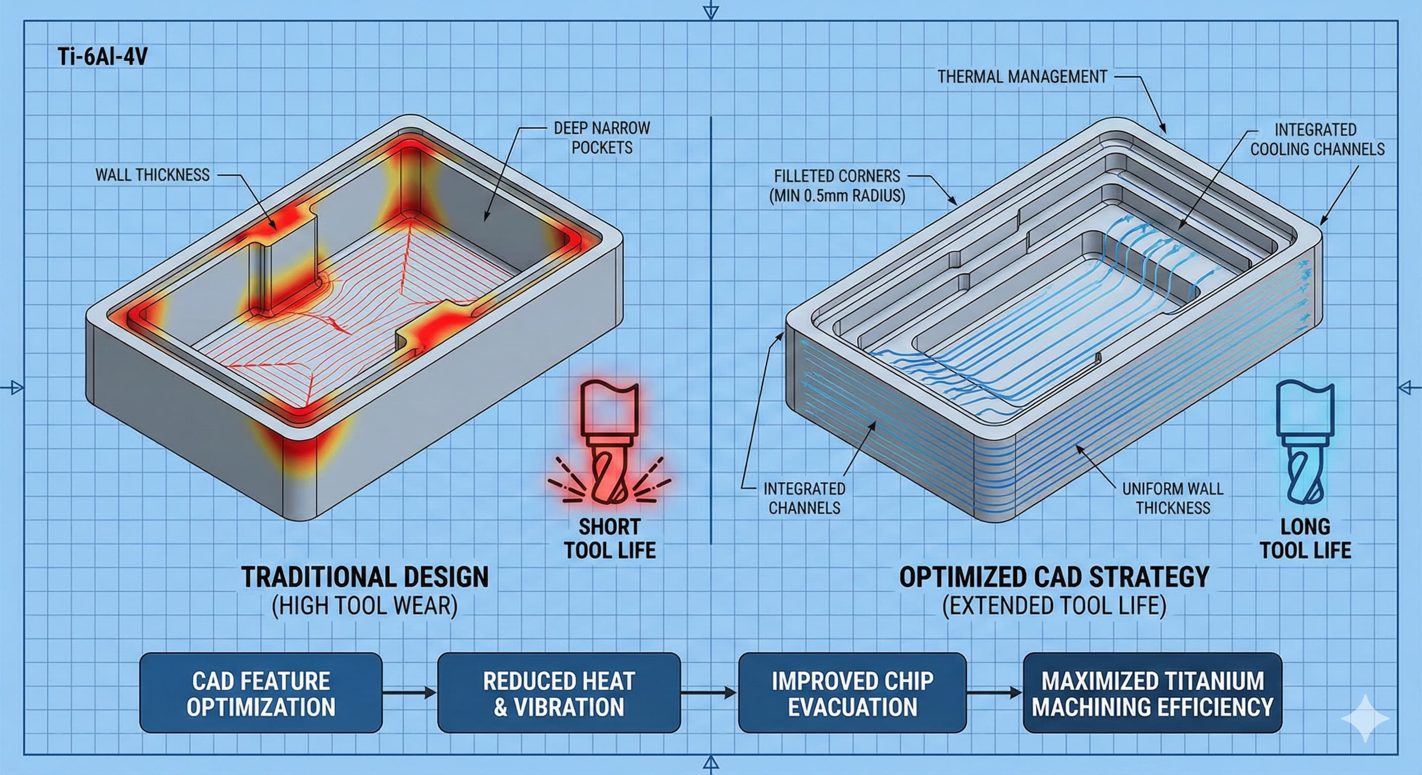
Titanium machining presents one of manufacturing's greatest challenges: balancing the exceptional properties of Ti-6Al-4V and other titanium alloys against their notorious tendency to destroy cutting tools. Tool wear rates in titanium can exceed steel machining by 300-500%, with carbide tools lasting mere minutes under suboptimal conditions. The solution lies not just in cutting parameters, but in strategic CAD design decisions that fundamentally alter the machining dynamics.
Key Takeaways
- Strategic feature orientation in CAD can reduce tool engagement time by up to 40%, dramatically extending tool life
- Proper corner radius design (minimum 0.5 mm) eliminates stress concentrators that accelerate carbide tool failure
- Material removal volume optimization through smart feature placement reduces total machining time and heat generation
- Integrated cooling channel design in complex parts enables continuous flood coolant access to critical cutting zones
Understanding Titanium's Tool Wear Mechanisms
Titanium's low thermal conductivity (16.4 W/m·K compared to aluminum's 237 W/m·K) creates a perfect storm for tool degradation. Heat generated at the cutting zone cannot dissipate through the workpiece, concentrating at the tool-chip interface where temperatures reach 800-1000°C. This thermal loading combines with titanium's chemical reactivity to create adhesive wear, where titanium atoms bond directly to carbide surfaces.
The work hardening characteristics of Ti-6Al-4V compound this challenge. Under cutting forces, the material's microstructure transforms from a relatively machinable α+β phase to a hardened structure that can reach 45-50 HRC in the immediate subsurface. This hardened layer, typically 0.05-0.15 mm deep, creates abrasive wear on subsequent tool passes.
Galling represents another critical failure mode. Titanium's tendency to cold-weld under pressure causes built-up edge formation on cutting tools. These welded deposits alter the tool geometry, increasing cutting forces and accelerating catastrophic failure through chipping or edge breakout.
CAD Strategies for Minimizing Tool Engagement
The most effective approach to reducing tool wear begins with strategic feature orientation during the design phase. Traditional machining approaches often position features based on functional requirements alone, ignoring the machining sequence implications. Smart CAD design considers the cutting tool's path length and engagement angle for every feature.
Pocket depth optimization represents a critical design decision. Deep pockets (depth-to-width ratios exceeding 3:1) create challenging evacuation conditions where chips cannot escape effectively. This leads to re-cutting, elevated temperatures, and rapid tool degradation. Design alternatives include stepped pocket configurations or multi-level machining strategies that maintain optimal depth-to-width ratios below 2:1.
Wall thickness consistency across part geometry eliminates varying cutting loads that cause tool deflection and premature wear. Maintaining uniform wall thickness of 2.0-3.0 mm throughout the design allows for consistent cutting parameters and predictable tool life. When thickness variation is unavoidable, gradual transitions over distances of at least 10 mm prevent sudden load changes.
Corner radii deserve particular attention in titanium applications. Sharp internal corners create stress concentrators that lead to tool breakage, while radii below 0.3 mm require small diameter tools prone to deflection and rapid wear. Optimal internal corner radii range from 0.5-1.5 mm, matching available carbide tool geometries while providing adequate strength for titanium's cutting forces.
Feature TypeTraditional DesignOptimized DesignTool Life ImprovementInternal Corners0.1-0.3 mm radius0.5-1.5 mm radius200-300%Pocket DepthDepth/Width > 3:1Depth/Width< 2:1150-250%Wall ThicknessVariable (1-5 mm)Consistent (2-3 mm)100-200%Surface TransitionsSharp changesGradual (>10 mm)75-150%
Advanced Feature Geometry for Tool Preservation
Ramping strategies must be considered during the CAD phase to ensure optimal tool entry conditions. Vertical plunge cuts into titanium create maximum cutting loads and thermal shock. Design features should incorporate ramping surfaces with angles between 2-5 degrees, allowing gradual tool engagement that distributes cutting forces over extended contact length.
Hole design requires particular consideration for titanium machining. Standard drilling operations create significant tool wear due to poor chip evacuation and concentrated heat generation. CAD designs should incorporate pre-machined chamfers or counterbores that enable drilling operations to start with reduced cutting loads. For critical holes, helical interpolation geometry should be designed into surrounding features to enable this superior machining approach.
Thread design modifications can dramatically impact tool life in titanium applications. Standard metric threads with 60-degree included angles create high cutting forces during threading operations. Where possible, modified thread forms with 45-50 degree included angles reduce cutting loads while maintaining adequate thread strength for most applications. Thread run-out geometry should provide adequate length (minimum 3 thread pitches) for gradual tool withdrawal.
For applications requiring precision CNC machining services, feature accessibility becomes paramount. Enclosed features requiring deep tool extensions should be redesigned as open geometries where possible. This approach enables the use of shorter, more rigid tools that resist deflection and maintain cutting edge integrity throughout extended machining cycles.
Material Removal Volume Optimization
Strategic material distribution in CAD designs can minimize total machining time and associated tool wear. The principle involves concentrating material removal in areas where cutting conditions can be optimized, while minimizing material in regions requiring challenging tool access or unfavorable cutting geometries.
Roughing allowances should be incorporated into the initial design to enable efficient material removal strategies. Rather than machining final dimensions directly from solid material, designs should include intermediate geometries that allow roughing operations with robust tools, followed by finishing passes with optimized cutting conditions. Typical roughing allowances for titanium range from 0.5-1.5 mm per surface, depending on part complexity.
Rib and web configurations significantly impact machining efficiency. Traditional rib designs with constant thickness often require extensive semi-finishing operations that accelerate tool wear. Tapered rib designs with thickness reducing from base to tip enable more efficient machining sequences while maintaining structural requirements. Base thickness should match available tool diameters (6-12 mm typical) while tip thickness can reduce to 2-3 mm minimum.
Boss design integration affects both tool access and cutting loads. Isolated bosses require individual tool approaches that increase total machining time and tool changes. Where functionally acceptable, boss features should be integrated into surrounding geometry or designed as continuous features that enable efficient tool paths with consistent cutting loads.
Thermal Management Through Design
Heat dissipation represents a critical factor in titanium tool life, requiring CAD designs that facilitate effective cooling strategies. Traditional flood coolant applications often fail to reach critical cutting zones, particularly in deep features or enclosed geometries. Design modifications can ensure coolant access where most needed.
Coolant channels should be integrated into part geometry during the design phase rather than added as afterthoughts. These channels, typically 4-6 mm diameter, provide directed coolant flow to critical cutting zones. Channel placement must consider machining sequence to ensure they remain intact through roughing operations while providing cooling for finishing passes.
Material thickness affects thermal mass and heat absorption characteristics. Thick sections (>20 mm) provide better heat sinking but may require internal cooling features. Thin sections (<5 mm) offer rapid heat dissipation but may suffer thermal distortion. Optimal thickness ranges for titanium applications fall between 8-15 mm, providing adequate thermal mass while enabling effective cooling.
Surface area optimization through design modifications can enhance natural convection cooling. Ribbed surfaces, stepped geometries, and integrated heat sink features increase surface area available for heat transfer. These modifications must be balanced against machining complexity, but can provide 15-30% improvements in cutting zone temperatures.
For high-precision results,Get your custom quote delivered in 24 hours from Microns Hub.
Tolerance and Surface Finish Considerations
Tolerance specification directly impacts tool selection and machining strategies for titanium parts. Tight tolerances (±0.025 mm or better) typically require finishing passes with light cutting loads, extending tool life but increasing machining time. The key lies in optimizing tolerance requirements to balance precision with manufacturing efficiency.
Critical dimensions should be concentrated on surfaces with favorable cutting geometries. External features generally enable better tool access and cutting conditions compared to internal features. Where possible, critical tolerances should be assigned to external surfaces or features accessible with short, rigid tools.
Surface finish requirements significantly affect tool wear patterns. Ra values below 0.8 μm typically require multiple finishing passes with minimal material removal per pass. This approach extends tool life through reduced cutting loads but increases total machining time. Surface finish optimization may involve specifying different requirements for functional versus cosmetic surfaces.
Form and position tolerances must consider titanium's elastic properties and potential for distortion during machining. Stress-relieving features such as symmetrical material removal and balanced cutting loads should be incorporated into designs requiring tight geometric tolerances. This approach minimizes distortion-induced tolerance violations while reducing cutting forces that accelerate tool wear.
Tolerance RangeRecommended ApproachExpected Tool LifeCost Impact±0.1 mmSingle finish passMaximum+15-25%±0.05 mmLight finish passesGood+25-35%±0.025 mmMultiple light passesModerate+40-60%±0.01 mmSpecialized toolingLimited+75-100%
Integration with Manufacturing Process Planning
CAD designs must consider the complete manufacturing sequence to optimize tool life across all operations. Feature sequencing affects workpiece rigidity, clamping requirements, and cutting load distribution. Strategic feature placement can minimize tool changes and enable optimized cutting parameters throughout the machining cycle.
Fixturing integration should be considered during design development rather than as a separate manufacturing concern.Holding tabs and clamping surfaces designed into the part geometry provide secure workpiece retention while minimizing setup time and reducing vibration that accelerates tool wear.
Tool access analysis during the CAD phase identifies potential interference issues that could require specialized tooling or extended tool lengths. Standard tool libraries should be referenced during design to ensure features can be machined with readily available, cost-effective tooling. Custom tool requirements should be minimized through design modifications where possible.
Setup reduction strategies through multi-operation part orientation can significantly reduce total machining time and associated tool wear. Designs should enable complete or near-complete machining in a single setup, minimizing workpiece handling and setup time. This approach requires careful consideration of draft angles, parting lines, and feature accessibility from multiple directions.
Cost-Benefit Analysis of Design Optimization
The economic impact of CAD optimization for titanium machining extends beyond simple tool cost reduction. Tool life improvements of 200-400% translate to reduced machine downtime, lower labor costs for tool changes, and improved part consistency through stable cutting conditions. These benefits often justify design modifications that might increase initial part complexity.
Machining time reduction through optimized designs typically ranges from 20-50% compared to traditional approaches. This improvement comes from reduced tool changes, optimized cutting parameters, and elimination of challenging machining operations. The time savings compound across production volumes, making design optimization increasingly valuable for higher quantity applications.
Quality improvements from stable cutting conditions reduce scrap rates and rework costs. Consistent tool performance throughout the machining cycle maintains dimensional accuracy and surface finish quality. This reliability is particularly valuable for aerospace and medical applications where part rejection costs are substantial.
When ordering from Microns Hub, you benefit from direct manufacturer relationships that ensure superior quality control and competitive pricing compared to marketplace platforms. Our technical expertise in titanium machining and comprehensive understanding of design optimization means every project receives the specialized attention titanium applications demand.
Advanced CAD Techniques and Software Integration
Modern CAD systems offer specialized tools for machining optimization that can be leveraged during the design phase. Machinability analysis features identify problematic geometries before manufacturing begins, enabling design modifications while changes remain cost-effective. These tools evaluate cutting tool access, engagement angles, and potential interference conditions.
Feature-based design approaches enable rapid evaluation of alternative geometries for improved machinability. Parametric modeling allows designers to quickly assess the impact of corner radius changes, wall thickness modifications, or feature relocations on manufacturing requirements. This capability accelerates the optimization process while maintaining design intent.
Manufacturing simulation integration provides early feedback on tool selection and cutting parameters. Advanced CAD systems can simulate complete machining sequences, identifying potential tool wear issues and optimization opportunities. This simulation capability enables proactive design modifications rather than reactive manufacturing problem-solving.
Collaboration tools within CAD systems facilitate communication between design and manufacturing teams. Built-in annotation and review capabilities enable manufacturing engineers to provide specific feedback on tool wear concerns and design optimization opportunities. This collaboration ensures manufacturing considerations are properly integrated into final designs.
Design rule checking can be customized for titanium machining requirements, automatically flagging geometries that may cause tool wear issues. Standard rules might include minimum corner radius requirements, maximum depth-to-width ratios, and wall thickness consistency checks. These automated checks prevent problematic geometries from progressing to manufacturing.
Case Studies and Implementation Examples
A typical aerospace bracket redesign demonstrates the impact of systematic CAD optimization for titanium machining. The original design featured sharp internal corners (0.2 mm radius), variable wall thickness (1-4 mm), and deep pockets with 4:1 depth-to-width ratios. Tool life averaged 15-20 minutes with frequent breakage due to thermal shock and cutting load variations.
The optimized design incorporated 0.8 mm internal radii, consistent 2.5 mm wall thickness, and stepped pocket geometry maintaining 1.8:1 maximum depth-to-width ratios. Integrated coolant channels provided direct cooling to critical cutting zones. Tool life improved to 80-120 minutes while maintaining all functional requirements and reducing total machining time by 35%.
Medical implant applications present unique challenges due to biocompatibility requirements and complex organic geometries. Traditional approaches often require extensive hand-finishing due to tool wear issues creating surface irregularities. Optimized CAD designs incorporate gradual transitions, optimized cutting angles, and strategic material distribution to enable consistent machining throughout the cutting cycle.
Similar optimization principles apply to cost reduction strategies across various manufacturing processes, where design modifications can significantly impact overall production economics through improved efficiency and reduced tooling costs.
Quality Control and Validation Methods
Verification of CAD optimization effectiveness requires systematic measurement of tool wear patterns, machining times, and part quality metrics. Baseline measurements from traditional designs provide comparison standards for evaluating improvement levels. Key metrics include average tool life, cutting time per part, surface finish consistency, and dimensional accuracy variation.
Tool wear analysis should examine both gradual wear patterns and catastrophic failure modes. Optimized designs typically show more predictable, gradual wear rather than sudden failure events. This predictability enables better production planning and reduces unexpected downtime from tool breakage.
Surface integrity evaluation becomes critical for titanium applications, particularly in aerospace and medical sectors. Optimized machining conditions should maintain consistent surface finish and minimize heat-affected zones that could compromise material properties. Regular surface integrity testing validates the effectiveness of CAD optimization strategies.
Statistical process control implementation tracks the consistency of optimized designs across production volumes. Control charts for tool life, machining time, and quality metrics identify when process conditions drift from optimal ranges. This monitoring enables proactive adjustments to maintain optimization benefits throughout production runs.
Future Trends and Emerging Technologies
Artificial intelligence integration in CAD systems promises automated optimization for titanium machining applications. Machine learning algorithms can analyze historical machining data to identify optimal design parameters and predict tool life based on geometric features. This capability will accelerate the optimization process while improving prediction accuracy.
Additive manufacturing integration offers new possibilities for complex internal geometries that enhance cooling and reduce material volume. Hybrid approaches combining additive pre-forms with optimized subtractive finishing enable geometries impossible with traditional manufacturing methods. These approaches require new CAD strategies that consider both additive and subtractive manufacturing constraints.
Advanced materials characterization provides better understanding of titanium's machining behavior under various conditions. Real-time monitoring of cutting forces, temperatures, and tool wear enables continuous optimization of cutting parameters based on actual performance rather than theoretical models. This feedback can inform CAD optimization strategies for improved effectiveness.
Digital twin technology enables virtual validation of CAD optimization strategies before physical implementation. Complete manufacturing process simulation, including tool wear prediction and thermal analysis, provides comprehensive evaluation of design modifications. This capability reduces the cost and time required for optimization validation while improving prediction accuracy.
Implementation Guidelines and Best Practices
Successful implementation of CAD optimization for titanium machining requires systematic approach and clear communication between design and manufacturing teams. Optimization guidelines should be documented and integrated into standard design procedures to ensure consistent application across projects.
Training programs for design engineers should emphasize the relationship between geometric features and machining challenges specific to titanium. Understanding cutting tool limitations, thermal management requirements, and material removal strategies enables designers to make informed optimization decisions during the design process rather than requiring extensive redesign later.
Collaboration protocols between design and manufacturing teams ensure manufacturing constraints are properly communicated and understood. Regular design reviews with manufacturing input can identify optimization opportunities early in the design cycle when changes remain cost-effective.
For organizations utilizing our manufacturing services, we provide comprehensive design review and optimization recommendations to ensure your titanium parts achieve optimal machinability while maintaining all functional requirements.
Frequently Asked Questions
What is the minimum corner radius recommended for internal features in titanium parts?
Internal corner radii should be minimum 0.5 mm for titanium machining applications. Smaller radii require delicate cutting tools prone to breakage and thermal damage. Optimal radii range from 0.8-1.5 mm, matching standard carbide tool geometries while providing adequate strength for titanium's cutting forces. Sharp corners below 0.3 mm typically result in tool life reductions of 70-80% compared to properly radiused features.
How does pocket depth-to-width ratio affect tool life in titanium machining?
Pocket depth-to-width ratios should remain below 2:1 for optimal tool life in titanium applications. Ratios exceeding 3:1 create poor chip evacuation conditions, leading to re-cutting, elevated temperatures, and accelerated tool wear. Deep pockets also require extended tool lengths that increase deflection and chatter. Stepped pocket designs or multi-level machining strategies maintain optimal ratios while achieving required part geometry.
What wall thickness provides the best balance between material removal and machining stability?
Consistent wall thickness between 2.0-3.0 mm provides optimal balance for titanium machining. Thinner walls lack rigidity and may vibrate during cutting, while thicker walls require excessive material removal. Thickness variations should be gradual over minimum 10 mm distances to prevent sudden cutting load changes that accelerate tool wear. Variable thickness designs often reduce tool life by 40-60% compared to consistent thickness approaches.
How should thread geometry be modified for improved tool life in titanium?
Standard 60-degree metric threads can be modified to 45-50 degree included angles where functionally acceptable, reducing cutting loads during threading operations. Thread run-out should provide minimum 3 pitch lengths for gradual tool withdrawal. External threads are preferable to internal threads due to better tool access and chip evacuation. Internal threads requiring tapping operations should incorporate chamfered starts and adequate lead-in geometry.
What role do coolant channels play in CAD design for titanium machining?
Integrated coolant channels, typically 4-6 mm diameter, should be designed into part geometry to provide directed cooling to critical cutting zones. Channel placement must consider machining sequence to remain intact through roughing while cooling finishing operations. Proper coolant delivery can reduce cutting zone temperatures by 150-250°C, extending tool life by 200-300%. Channels should be positioned within 10-15 mm of critical cutting areas for maximum effectiveness.
How do tolerance requirements impact tool selection and wear in titanium machining?
Tighter tolerances (±0.025 mm or better) require finishing passes with reduced cutting loads, extending tool life but increasing machining time. Critical dimensions should be placed on external features or surfaces with favorable cutting geometries where possible. Tolerances below ±0.01 mm may require specialized tooling and cutting parameters that significantly impact tool life and cost. Tolerance optimization can reduce machining costs by 25-40% while maintaining functional requirements.
What CAD features should be avoided to prevent excessive tool wear in titanium?
Avoid sharp internal corners below 0.3 mm radius, deep enclosed pockets with poor tool access, variable wall thickness creating sudden load changes, and features requiring extended tool lengths with high length-to-diameter ratios. Intersecting features creating complex cutting geometries should be simplified where possible. Blind holes deeper than 5 diameters and internal threads in deep bores should be redesigned as external features when functionally acceptable. These problematic features can reduce tool life by 60-80% compared to optimized alternatives.
MICRONS HUB DV Ε.Ε. · VAT: EL803129638 · GEMI: 190254227000 · Industrial Area, Street B, Number 4, 71601 Heraklion, Crete, Greece