Designing for Fixturing: How to Add Holding Tabs to Complex CNC Parts
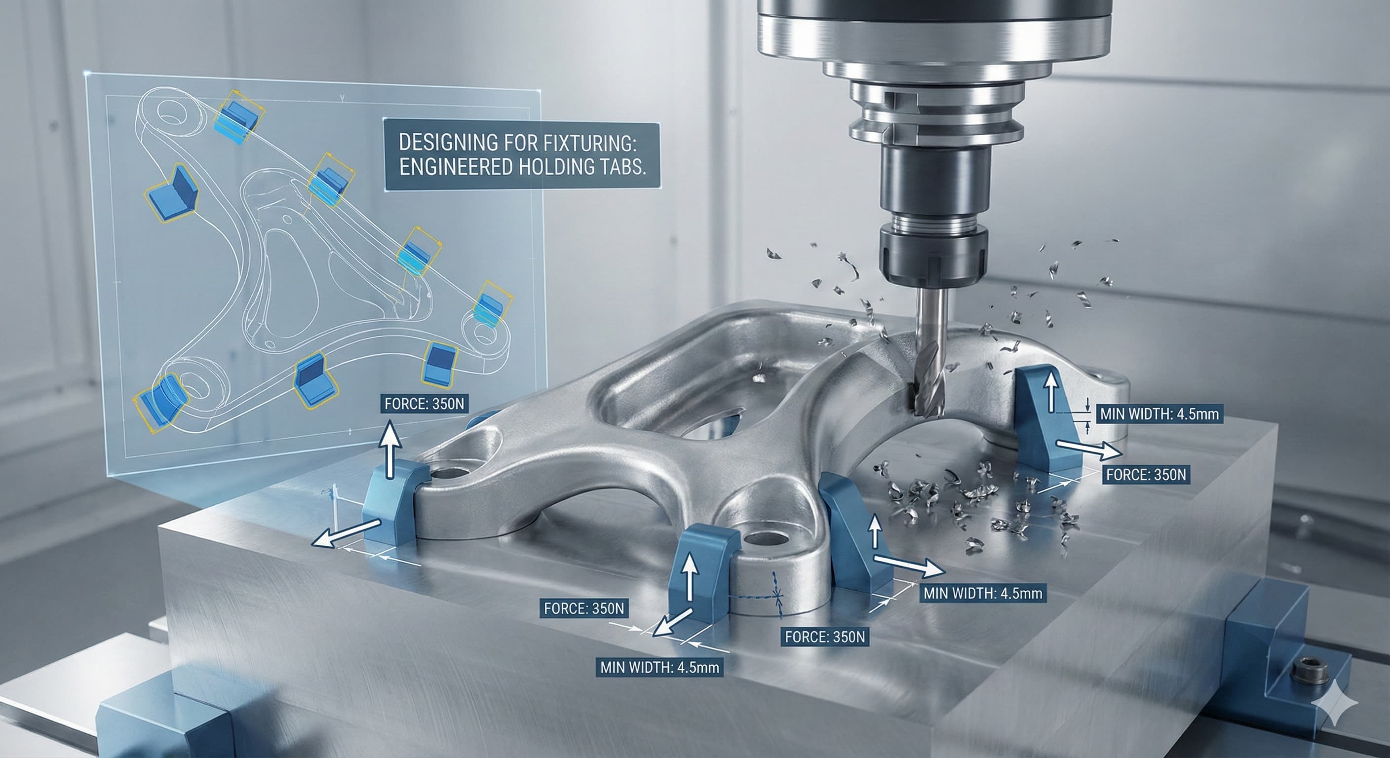
Machining complex parts presents an engineering paradox: the more sophisticated the geometry, the greater the challenge of securing it during fabrication. When your CNC program calls for five-axis operations on thin-walled aerospace brackets or intricate medical device housings, standard vises and three-jaw chucks become inadequate. The solution lies in strategic fixture design with properly engineered holding tabs – temporary sacrificial connections that maintain part integrity throughout the machining cycle.
Key Takeaways
- Holding tabs must be sized according to cutting forces: minimum 3-5 mm width for aluminum parts under 500g, scaling proportionally for heavier components
- Strategic tab placement at stress concentration points reduces vibration by up to 60% compared to perimeter-only fixturing
- Material-specific tab geometries optimize separation: 45-degree chamfers for aluminum alloys, straight cuts for steels above 40 HRC
- Proper tab design reduces total machining time by 25-35% through elimination of multiple setups and re-fixturing operations
Understanding Fixturing Fundamentals for Complex Geometries
The physics of material removal creates dynamic forces that challenge part stability throughout the machining process. When cutting forces exceed the holding strength of your fixture system, parts shift, surfaces deflect, and tolerances drift beyond acceptable limits. This becomes particularly problematic with complex geometries featuring thin walls, deep pockets, or cantilevered features that amplify vibration and deflection.
Holding tabs function as temporary structural reinforcements, distributing cutting forces across multiple contact points while maintaining access to critical machining surfaces. Unlike traditional clamping methods that rely on external pressure points, tabs integrate directly with the part geometry, creating a monolithic structure during machining operations. The key lies in understanding that tabs aren't just attachment points – they're engineered elements that must account for material properties, cutting forces, and post-machining separation requirements.
For complex parts requiring injection molding services or subsequent processing, tab placement becomes even more critical as they may interfere with downstream operations. The initial design phase must consider the entire manufacturing workflow, not just the immediate CNC requirements.
Tab Geometry and Sizing Calculations
Proper tab dimensioning requires understanding the relationship between cutting forces, material properties, and safety factors. The fundamental calculation begins with determining the maximum cutting force your operation will generate. For aluminum 6061-T6 parts, typical face milling operations generate forces of 200-400 N per millimeter of cutter engagement, while steel components can see forces exceeding 800 N/mm.
Tab cross-sectional area must provide adequate tensile strength with appropriate safety factors. For aluminum alloys, minimum tab width should equal 0.8 times the material thickness for parts under 100g, increasing to 1.2 times thickness for components exceeding 500g. The relationship isn't linear – larger parts require proportionally stronger tabs due to increased moment arms and dynamic effects.
Material GradePart Weight (g)Minimum Tab Width (mm)Recommended Thickness (mm)Safety FactorAl 6061-T650-2003.01.53.0Al 6061-T6200-5004.52.03.5Al 7075-T650-2002.51.22.8Steel 1018200-5003.51.84.0Stainless 316L200-5004.02.24.2
Tab geometry extends beyond simple rectangular cross-sections. Stress risers at tab-to-part junctions concentrate forces, potentially causing premature failure or unwanted crack propagation into the finished part. Incorporating 0.5-1.0 mm fillets at these junctions reduces stress concentration by 40-60% while maintaining adequate holding strength. For parts requiring superior surface finish, these transition zones may require additional finishing operations post-separation.
Strategic Tab Placement for Optimal Support
Tab positioning determines both machining success and part quality outcomes. The fundamental principle involves creating a stable tripod configuration that resists the six degrees of freedom – three translational and three rotational axes. For complex geometries, this often requires four or more tabs strategically located to counteract specific force vectors generated during machining operations.
Placement analysis begins with identifying critical features that generate the highest cutting forces. Deep pocket machining, slot operations, and contour finishing create directional forces that must be anticipated and countered. Position tabs perpendicular to primary force directions when possible, creating the most effective resistance to part movement. When perpendicular placement isn't feasible due to geometric constraints, angle tabs at 45-60 degrees to the force vector while increasing cross-sectional area by 20-30% to compensate for reduced effectiveness.
Consider material removal sequence during tab placement. Operations that remove substantial material volume alter the part's dynamic characteristics, potentially rendering initial tab locations inadequate for later operations. Progressive tab removal strategies allow for fixture reconfiguration mid-cycle, maintaining optimal support throughout the machining process. This approach particularly benefits complex aerospace components where material removal exceeds 70-80% of the initial billet volume.
Material-Specific Considerations and Optimization
Different materials exhibit unique behaviors during machining operations, requiring tailored approaches to tab design and implementation. Aluminum alloys, particularly 6061-T6 and 7075-T6, machine readily but generate significant heat that can affect tab integrity during extended operations. These materials benefit from tabs designed with heat dissipation in mind – larger cross-sections and strategic positioning away from high-heat zones when possible.
Steel components present different challenges, with higher cutting forces requiring more robust tab designs. The increased material strength works both for and against the designer – tabs can withstand higher loads but require more aggressive separation techniques post-machining. For steels above 35 HRC, consider pre-scored tab designs that facilitate controlled separation while maintaining adequate holding strength during machining.
Material TypeCutting Force FactorHeat GenerationTab Separation MethodSurface Finish ImpactAl 6061-T61.0x baselineModerateBand saw/filingRa 1.6-3.2 μmAl 7075-T61.2x baselineModerate-HighBand saw/filingRa 1.6-3.2 μmSteel 10182.1x baselineHighAbrasive cut-offRa 6.3-12.5 μmStainless 316L1.8x baselineVery HighWire EDM preferredRa 3.2-6.3 μmTitanium Ti-6Al-4V1.6x baselineExtremeWire EDM requiredRa 1.6-3.2 μm
Exotic materials like titanium alloys and Inconel require specialized approaches due to their work-hardening characteristics and extreme heat generation. These materials may necessitate active cooling systems directed at tab locations, or alternative strategies like sacrificial cooling tabs designed specifically for heat dissipation rather than structural support.
Advanced Fixturing Strategies for Multi-Axis Operations
Five-axis machining introduces rotational dynamics that standard fixturing methods cannot accommodate effectively. As the part rotates through various orientations, gravitational forces shift, and cutting force vectors change direction continuously. Traditional tabs positioned for three-axis operations may become inadequate or even counterproductive when the workpiece orientation changes.
Multi-axis tab design requires analyzing force vectors across all programmed orientations, identifying the worst-case scenarios for each tab location. This analysis often reveals the need for asymmetric tab designs – tabs that appear oversized for certain orientations but provide critical support during high-stress operations in other orientations. The key is designing for the worst case while accepting over-engineering for less demanding operations.
For high-precision results,Request a free quote and get pricing in 24 hours from Microns Hub.
Consideration must also extend to clearance requirements for rotating heads and extended tooling. Tabs positioned adequately for spindle clearance in one orientation may interfere with tooling in another orientation. Stepped tab designs provide one solution – full-height support where needed with reduced sections for clearance requirements. This approach maintains structural integrity while ensuring complete program execution without interference.
Cost Implications and Design Trade-offs
Holding tab implementation represents a balance between manufacturing efficiency and post-processing costs. While tabs reduce setup time and improve machining accuracy, they add material volume that must be purchased and subsequently removed. For high-volume production, these costs multiply significantly, making optimization critical for economic success.
The relationship between tab size and machining cost isn't linear. Undersized tabs lead to scrapped parts, requiring complete re-manufacturing at full cost. Oversized tabs increase material costs and post-processing time but provide insurance against failure. The optimal solution typically involves modest over-design – 10-20% above calculated minimums – providing adequate safety margin without excessive cost penalty.
When designing complex parts that may later require our manufacturing services across multiple processes, consider how tab placement affects downstream operations. Strategic positioning can eliminate interference with secondary operations like anodizing racks, heat treatment fixtures, or inspection equipment. This holistic approach reduces total manufacturing cost even if initial machining costs increase slightly.CNC machining cost optimization often requires this broader perspective to achieve meaningful savings.
Post-Machining Tab Removal and Finishing
The tab removal process significantly impacts final part quality and must be considered during initial design phases. Different separation methods leave characteristic surface textures and may introduce residual stresses that affect part performance. Planning for separation during design allows optimization of both tab geometry and removal processes.
Band saw separation works well for aluminum alloys and mild steels, leaving surfaces that respond well to filing and sanding operations. For production quantities, automated band saw systems can process multiple parts simultaneously, reducing labor costs while maintaining consistency. However, band saw operations typically leave surfaces with Ra values of 6.3-12.5 μm, requiring additional finishing for critical applications.
Wire EDM provides superior surface quality and precise control but increases processing costs significantly. This method becomes cost-effective for high-value parts requiring tight tolerances or superior surface finish. Wire EDM also eliminates mechanical stresses associated with cutting operations, preventing distortion in stress-sensitive components like thin-walled aerospace structures.
Separation MethodSuitable MaterialsSurface Finish (Ra μm)Cost per Cut (€)Processing TimeHand FilingAll soft materials1.6-6.38-1515-30 minBand SawAl, Steel<35 HRC6.3-12.52-52-5 minAbrasive Cut-offAll materials12.5-253-83-8 minWire EDMAll conductive0.8-3.225-6020-45 minLaser CuttingThin sections<5mm3.2-6.315-351-3 min
Integration with CAD/CAM Systems
Modern CAD/CAM systems provide powerful tools for tab design and optimization, but effective implementation requires understanding their capabilities and limitations. Parametric modeling allows rapid iteration through different tab configurations, enabling optimization studies that would be impractical with traditional drafting methods.
CAM software increasingly includes fixturing modules that analyze cutting forces and recommend tab placement based on programmed operations. These systems excel at identifying high-force operations and suggesting reinforcement locations, but they typically require experienced oversight to account for material-specific behaviors and manufacturing constraints not encoded in standard databases.
Simulation capabilities allow virtual testing of fixturing strategies before committing to production. Force analysis modules can predict deflections and identify potential failure modes, while dynamic simulation reveals resonance frequencies that could cause chatter or surface finish problems. However, these simulations require accurate material properties and cutting force models to provide reliable results.
Quality Control and Validation Strategies
Effective tab design requires validation through both analytical and empirical methods. Finite element analysis provides insight into stress distributions and deflection patterns, allowing optimization before physical prototyping. However, FEA models must account for dynamic effects and tool-workpiece interactions that static analysis cannot capture completely.
Physical validation typically begins with prototype parts machined under production conditions. Measuring deflections during machining operations validates analytical predictions and reveals unexpected behaviors. Accelerometer monitoring can identify resonance frequencies and vibration patterns that affect surface finish quality.
When ordering from Microns Hub, you benefit from direct manufacturer relationships that ensure superior quality control and competitive pricing compared to marketplace platforms. Our technical expertise and personalized service approach means every project receives the attention to detail required for optimal fixturing solutions, whether dealing with complex aerospace components or high-precision medical devices.
Production validation should include statistical process control methods to monitor tab performance over extended runs. Tracking dimensional accuracy, surface finish variation, and tab failure rates provides data for continuous improvement initiatives. This approach identifies degradation patterns before they affect part quality, allowing proactive adjustments to maintain process capability.
Industry-Specific Applications and Requirements
Different industries impose unique requirements on fixturing strategies, driving specialized approaches to tab design and implementation. Aerospace applications demand exceptional dimensional stability and traceability, often requiring documented analysis of fixture adequacy and validation testing. Medical device manufacturing adds biocompatibility concerns that may restrict material choices and separation methods.
Automotive applications typically emphasize cost optimization and cycle time reduction, favoring robust tab designs that enable automated processing. The higher production volumes justify sophisticated fixture systems with automated tab removal and finishing operations. These systems often incorporate mistake-proofing features to prevent processing errors that could affect large production quantities.
Electronics manufacturing requires consideration of thermal expansion coefficients and electromagnetic compatibility. Tabs must maintain dimensional stability across temperature ranges while avoiding materials that could affect electromagnetic performance. This often drives selection of specific aluminum alloys or composite materials with tailored thermal properties.
Frequently Asked Questions
What minimum safety factor should I use when calculating tab cross-sectional area?
For aluminum alloys, use a minimum safety factor of 3.0 for static loads, increasing to 4.0-5.0 for dynamic machining operations. Steel components require safety factors of 3.5-4.5 depending on hardness and cutting conditions. These factors account for stress concentrations, material variability, and unexpected force spikes during machining operations.
How do I determine the optimal number of tabs for a complex part?
Start with a minimum of three tabs positioned in a triangular configuration to resist all degrees of freedom. Add tabs strategically based on part geometry – one tab per 100-150 mm of perimeter for thin-walled parts, additional tabs near stress concentration points like sharp corners or thin sections. Complex five-axis operations may require 6-8 tabs to maintain stability through all orientations.
Can I reuse tabs for multiple production runs?
No, tabs are sacrificial elements designed for single-use applications. Attempting to reuse tabs compromises structural integrity and dimensional accuracy. Each part requires fresh tabs properly integrated with the base geometry. For production efficiency, design tab geometries that minimize material waste and optimize separation processes.
What's the best method for removing tabs from titanium parts?
Wire EDM provides optimal results for titanium alloys due to their work-hardening characteristics and difficulty with conventional cutting methods. Alternative approaches include abrasive cutoff wheels with proper coolant flow, but these leave rougher surfaces requiring additional finishing. Never attempt hand filing on titanium tabs as work hardening makes material removal extremely difficult.
How do tab locations affect part distortion after separation?
Asymmetric tab placement can introduce residual stresses that cause distortion when tabs are removed. Design symmetric tab configurations when possible, or use stress-relief operations before final separation. Parts with thin walls or high aspect ratios are particularly susceptible to distortion and may require specialized fixturing strategies or post-separation stress relieving.
Should tab thickness match the parent material thickness?
Not necessarily. Tab thickness should be determined by structural requirements rather than matching parent material. Thin-wall parts often benefit from thicker tabs that provide additional stiffness during machining. Conversely, thick parts may use thinner tabs to reduce material costs and simplify separation, provided they meet strength requirements.
How do I prevent tabs from interfering with five-axis machining operations?
Analyze tool paths across all programmed orientations to identify potential interference zones. Use stepped tab designs with full-height sections for structural support and reduced-height sections for tool clearance. Consider programmable tab removal – removing specific tabs mid-cycle as they become unnecessary or problematic for subsequent operations.
MICRONS HUB DV Ε.Ε. · VAT: EL803129638 · GEMI: 190254227000 · Industrial Area, Street B, Number 4, 71601 Heraklion, Crete, Greece