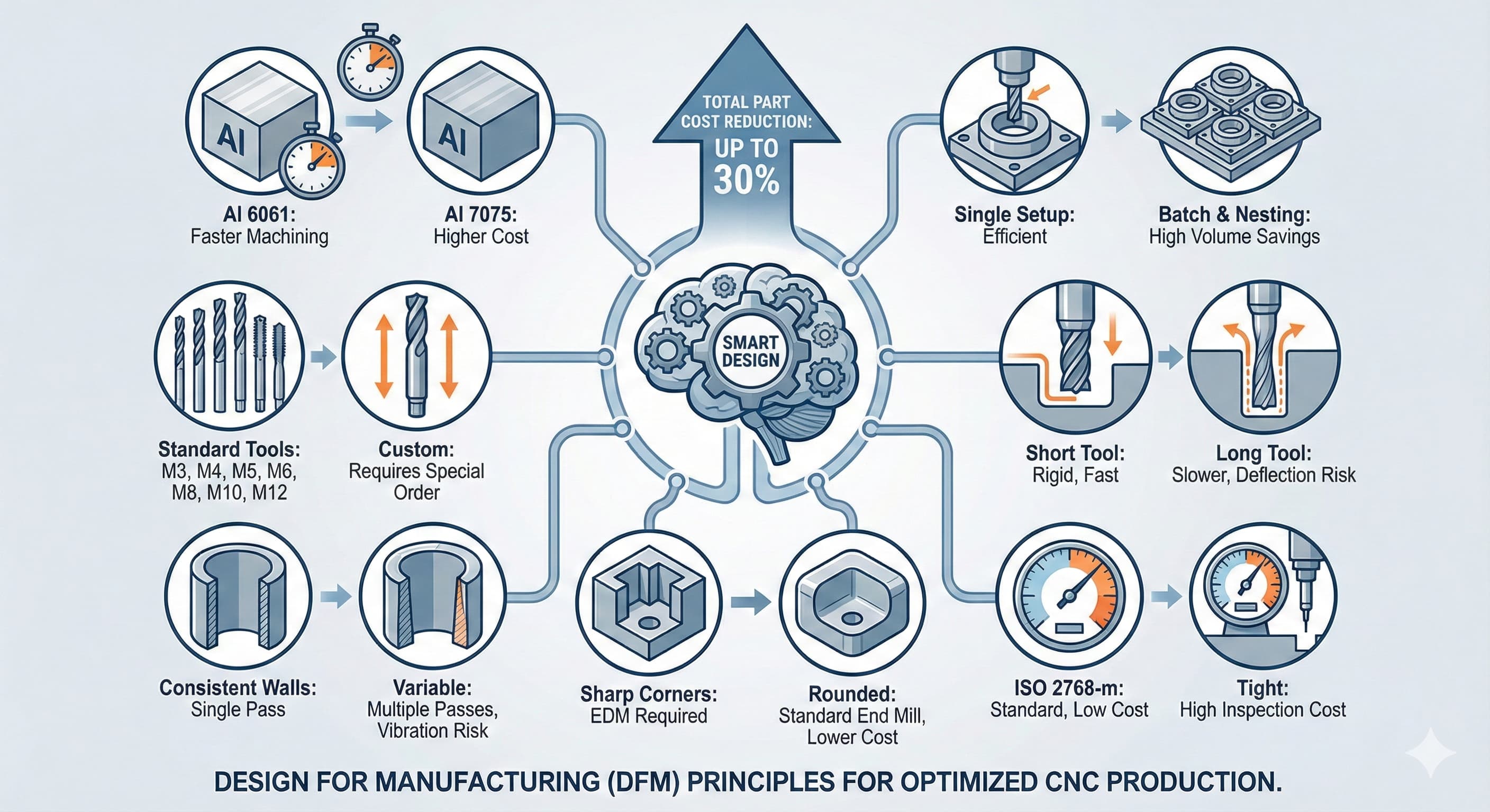
CNC Machining Cost Drivers: 7 Design Tweaks to Reduce Part Price by 30%
Most engineers focus on functionality first and cost second—a costly mistake when it comes to CNC machining. After two decades of optimizing manufacturing processes at Microns Hub, I've identified recurring design patterns that inflate part costs by 20-50% without adding meaningful value. The solution isn't cheaper materials or lower-quality suppliers; it's intelligent design modifications that work with CNC capabilities rather than against them.
Key Takeaways
- Standard tooling accessibility reduces machining time by 40-60% compared to complex geometries requiring specialized cutters
- Material selection beyond alloy type—considering machinability ratings and stock availability—impacts total cost more than raw material price
- Feature consolidation through design for manufacturing (DFM) principles can eliminate secondary operations entirely
- Tolerance specification strategy: applying tight tolerances only where functionally critical reduces inspection time and scrap rates significantly
Understanding CNC Cost Structure: The Hidden Variables
CNC machining costs break down into five primary categories, but most engineers only consider two. Beyond obvious material and machine time costs, setup complexity, tooling requirements, and quality assurance protocols often represent 40-70% of total part cost for low-to-medium volume production.
Setup time scales disproportionately with geometric complexity. A simple rectangular block with standard holes machines in one setup, while a part requiring multiple orientations multiplies both setup time and fixture costs. Each additional setup adds 15-45 minutes of non-cutting time, depending on part complexity and fixturing requirements.
Tooling costs compound when designs demand specialized cutters. Standard end mills in 3mm, 6mm, 10mm, and 20mm diameters handle 85% of machining operations efficiently. Requiring a 2.3mm end mill for a specific pocket depth doubles tool cost and increases lead time for tool procurement.
Cost ComponentTypical PercentagePrimary DriversDesign ImpactRaw Material20-35%Alloy type, stock size, availabilityHighMachine Time25-40%Cutting speed, tool path efficiencyVery HighSetup & Fixturing15-25%Number of setups, fixture complexityVery HighTooling8-15%Tool type, replacement frequencyHighQuality Assurance5-12%Tolerance requirements, inspection timeMedium Design Tweak #1: Optimize Material Selection Beyond Alloy Type
Engineers typically select materials based on mechanical properties alone, ignoring machinability factors that dramatically affect manufacturing cost. Aluminum 6061-T6 and 7075-T6 both meet strength requirements for many aerospace applications, but 6061-T6 machines 40% faster due to superior chip formation and lower tool wear rates.
Machinability ratings quantify cutting efficiency across different alloys. The American Iron and Steel Institute (AISI) rates materials on a scale where AISI 1212 steel equals 100%. Aluminum 6061-T6 rates 90-95%, while 7075-T6 rates 70-75%. This 20-point difference translates directly to cycle time variations.
Stock availability represents another hidden cost driver. Specifying 25.4mm thick plate when standard stock comes in 25mm or 30mm sizes adds material waste and potential sourcing delays. European suppliers typically stock metric dimensions: 10mm, 15mm, 20mm, 25mm, 30mm, 40mm, 50mm thicknesses for aluminum plate.
MaterialMachinability RatingCutting Speed (m/min)Tool Life FactorRelative Cost/HourAl 6061-T690-95300-5001.01.0Al 7075-T670-75200-3500.71.4Stainless 316L45-50120-1800.42.5Titanium Ti-6Al-4V20-2560-1200.24.8 Design Tweak #2: Standardize Hole Sizes and Thread Specifications
Custom hole diameters force tool changes and reduce cutting parameters. Standard drill bit sizes in metric progression (3mm, 4mm, 5mm, 6mm, 8mm, 10mm, 12mm) run at optimal feeds and speeds, while a 4.3mm hole requires either drilling undersize and reaming or running a standard drill at reduced parameters.
Thread specifications follow similar logic. ISO metric threads (M3, M4, M5, M6, M8, M10, M12) utilize standard tap sizes and proven cutting parameters. Custom threads require special taps, longer cycle times, and higher scrap risk due to tap breakage potential.
Hole depth-to-diameter ratios significantly impact drilling efficiency and tool life. Maintaining ratios below 3:1 for standard twist drills and 5:1 for specialized deep-hole drills optimizes chip evacuation and prevents work hardening. A 6mm diameter hole should extend maximum 18mm deep using standard tooling.
Counter-bore and counter-sink operations add complexity when dimensions don't align with standard fastener requirements. ISO 4762 socket head cap screws define specific counter-bore diameters and depths. M6 screws require 10mm diameter counter-bores with 6mm depth—deviating from these standards increases machining time without functional benefit.
Design Tweak #3: Implement Consistent Wall Thickness Strategy
Variable wall thickness demands multiple cutting passes with different tools, while consistent thickness enables single-pass operations with optimized cutting parameters. Thin walls below 1.5mm thickness in aluminum or 2mm in steel introduce vibration challenges requiring reduced cutting speeds and specialized workholding.
Pocket operations benefit significantly from consistent floor thickness. Programming software optimizes tool paths when material removal remains uniform throughout the cutting operation. Variable depth pockets require multiple roughing passes and increase cycle time proportionally.
Draft angles eliminate secondary machining operations for parts requiring post-machining assembly or coating processes. Incorporating 0.5-2.0 degree draft angles on vertical walls simplifies part extraction from fixtures and reduces burr formation during cutting operations.
For high-precision results, upload your CAD files to the Microns Hub instant quote engine.
Design Tweak #4: Minimize Feature Complexity Through Geometric Optimization
Complex geometric features exponentially increase programming time and tool path calculation complexity. Sharp internal corners require EDM finishing or multiple tool passes with progressively smaller end mills. Specifying 0.5mm radius corners instead of sharp corners eliminates secondary operations while maintaining functional performance for most applications.
Undercuts and reverse draft angles force additional setups or specialized tooling. Five-axis machining capabilities handle some complex geometries in single setups, but programming complexity and setup time often exceed cost savings from reduced handling. Eliminating undercuts through design revision typically reduces total cost while improving part strength through better stress distribution.
Surface finish requirements drive cutting parameter selection and final pass strategies. Ra 1.6μm surface finish achieves through standard machining parameters, while Ra 0.8μm requires additional finishing passes at reduced feed rates. Mirror finishes below Ra 0.4μm demand secondary polishing operations adding significant cost and lead time.
Feature TypeStandard ApproachTime MultiplierCost ImpactDFM AlternativeSharp Internal CornerMultiple tool passes + EDM3.5x+250%0.5mm radius cornerDeep Narrow SlotPlunge cutting + side milling2.8x+180%Wider slot or through-holeComplex Undercut5-axis or multiple setups4.2x+320%Eliminate or simplify geometryVery Thin Wall (<1mm)Light cuts, special fixtures2.2x+120%Increase to 1.5mm minimum Design Tweak #5: Strategic Tolerance Application
Tolerance specification represents the most common cost inflation factor in precision machining. ISO 2768 general tolerances handle most functional requirements without specific callouts. Medium grade (ISO 2768-m) provides ±0.1mm for dimensions up to 30mm, ±0.15mm for 30-120mm dimensions, and ±0.2mm for 120-400mm dimensions.
Critical tolerances requiring statistical process control (SPC) monitoring add inspection time and potential rework costs. Each dimension requiring coordinate measuring machine (CMM) verification adds 2-5 minutes inspection time plus documentation requirements. Limiting tight tolerances to functionally critical features reduces quality assurance overhead significantly.
Geometric dimensioning and tolerancing (GD&T) application following ASME Y14.5 standards communicates design intent more effectively than traditional plus/minus tolerancing. However, complex GD&T schemes requiring specialized inspection equipment increase cost without corresponding functional benefit in many applications.
Position tolerances for hole patterns demonstrate this principle clearly. A ±0.05mm position tolerance on a bolt circle requires CMM inspection, while ±0.1mm tolerance enables go/no-go gauge verification at one-third the inspection cost.
Design Tweak #6: Optimize Machining Access and Tool Clearance
Tool access limitations force longer tools with reduced rigidity, increasing vibration and limiting cutting parameters. Standard end mill length-to-diameter ratios of 3:1 or 4:1 provide optimal rigidity for most applications. Requiring 6:1 or higher ratios reduces cutting speeds by 30-50% and increases tool deflection risk.
Clearance requirements around machined features enable larger, more rigid tooling selection. A 20mm end mill removes material 4x faster than a 10mm end mill when sufficient clearance exists. Pocket operations benefit particularly from generous corner radii matching available tool sizes.
Fixture design integration during part design phase eliminates interference issues and reduces setup complexity. Standard vise jaw spacing, rotary table dimensions, and workholding constraints should influence design decisions early in the development process rather than forcing expensive custom fixturing solutions.
Programming accessibility affects both initial programming time and future modification efficiency. Features located in difficult-to-access areas require conservative cutting parameters and extensive tool path verification, increasing both programming time and cycle time.
Design Tweak #7: Batch Processing and Feature Consolidation
Feature consolidation reduces tool changes and optimizes cutting sequences. Grouping all drilling operations enables single tool setup with optimized parameters across multiple hole sizes. Sequential pocket operations with consistent depths streamline roughing and finishing passes.
Secondary operation elimination through primary setup optimization represents significant cost reduction opportunity. Parts requiring drilling, tapping, and counter-boring operations complete efficiently when hole locations accommodate single-setup accessibility. Complex parts requiring flip operations or multiple workholding setups multiply handling time and introduce positional accuracy challenges.
Batch-friendly design considerations enable efficient production scaling. Parts designed for simple fixturing and consistent tool requirements process efficiently in quantities from prototype through production volumes. Our manufacturing services optimize setup procedures for volume-appropriate production methods.
Material utilization optimization through nesting-friendly geometries reduces raw material waste and enables efficient programming for multiple-part setups. Rectangular or circular boundary profiles nest more efficiently than complex external profiles requiring individual stock pieces.
Design StrategyTime SavingsCost ReductionQuality ImpactImplementation DifficultyStandard Tool Sizes20-35%15-28%ImprovedLowConsistent Wall Thickness15-25%12-20%NeutralMediumSimplified Tolerances5-15%8-18%NeutralLowFeature Consolidation25-40%20-35%ImprovedHighMaterial Optimization10-20%15-25%ImprovedMedium Implementation Strategy: Systematic Design Review Process
Implementing these cost reduction strategies requires systematic design review integration into existing development processes. Early-stage DFM review identifies optimization opportunities before design freeze, when modifications remain relatively simple and inexpensive.
CAD model analysis using manufacturing simulation software predicts machining sequences and identifies potential issues before physical production. Software tools like CAMWorks, Mastercam, or Fusion 360 provide realistic cycle time estimates and highlight problematic features requiring design attention.
Cross-functional collaboration between design engineers and manufacturing engineers ensures optimal balance between functional requirements and production efficiency. Regular design reviews including manufacturing input prevent costly redesign cycles and accelerate time-to-market objectives.
Documentation standards incorporating DFM guidelines enable consistent application across multiple projects and team members. Standardized design rules, preferred material specifications, and approved tolerance schemes reduce design variation and enable more efficient quoting and production planning.
Measuring Cost Reduction Success
Quantifying cost reduction achievements requires baseline establishment and systematic tracking across multiple cost components. Total part cost includes material, machining time, setup time, tooling consumption, and quality assurance overhead—each responding differently to specific design modifications.
Cycle time reduction measurement provides the most direct manufacturing efficiency indicator. Comparing actual machining time before and after design optimization quantifies improvement magnitude and validates theoretical predictions from simulation software.
Quality metrics including first-pass yield rates and scrap percentages indicate design robustness improvements beyond simple cost reduction. Simplified designs typically demonstrate improved manufacturability through reduced variation and higher process capability indices.
Long-term cost tracking reveals optimization strategy effectiveness across production volumes and time periods. Initial setup complexity reduction benefits multiply across higher production quantities, while material optimization provides consistent benefits regardless of volume levels.
Frequently Asked Questions
What's the most effective single design change for reducing CNC machining costs?
Standardizing hole sizes and thread specifications typically provides 15-25% cost reduction with minimal design impact. Using standard metric drill sizes (3mm, 4mm, 5mm, 6mm, 8mm, 10mm) and ISO metric threads eliminates special tooling requirements and enables optimal cutting parameters throughout production.
How do tolerance specifications affect total part cost?
Tight tolerances below ±0.05mm can increase part cost by 30-80% through additional inspection requirements and potential rework. Applying ISO 2768 general tolerances for non-critical dimensions and reserving tight tolerances only for functionally critical features optimizes cost-performance balance effectively.
Which materials offer the best machinability-to-performance ratio for cost optimization?
Aluminum 6061-T6 provides excellent machinability (90-95 rating) with good strength properties for most applications. For steel components, 1018 or 12L14 grades offer superior machinability compared to stainless alloys while maintaining adequate strength for many structural applications.
How does feature complexity impact machining time and cost?
Complex features requiring specialized tooling or multiple setups can increase part cost by 200-400%. Sharp internal corners, deep narrow slots, and complex undercuts particularly impact cost through extended programming time, specialized tooling requirements, and reduced cutting parameters.
What wall thickness guidelines minimize machining costs while maintaining structural integrity?
Maintaining minimum wall thickness of 1.5mm for aluminum and 2.0mm for steel eliminates vibration issues and enables standard cutting parameters. Consistent wall thickness throughout the part enables single-pass operations and optimized tool path programming.
How do setup requirements affect small batch production costs?
Each additional setup adds 15-45 minutes of non-cutting time, significantly impacting small batch economics. Designing parts for single-setup machining can reduce total production time by 40-60% for quantities below 50 pieces, making prototyping and low-volume production more cost-effective.
What's the relationship between surface finish requirements and machining cost?
Surface finish requirements below Ra 1.6μm increase machining time exponentially. Ra 0.8μm requires 40-60% additional finishing time, while Ra 0.4μm demands secondary polishing operations adding 150-300% cost premium over standard machined finishes.
MICRONS HUB DV Ε.Ε. · VAT: EL803129638 · GEMI: 190254227000 · Industrial Area, Street B, Number 4, 71601 Heraklion, Crete, Greece