Panel Stiffeners: Adding Ribs and Flanges to Prevent "Oil Canning"
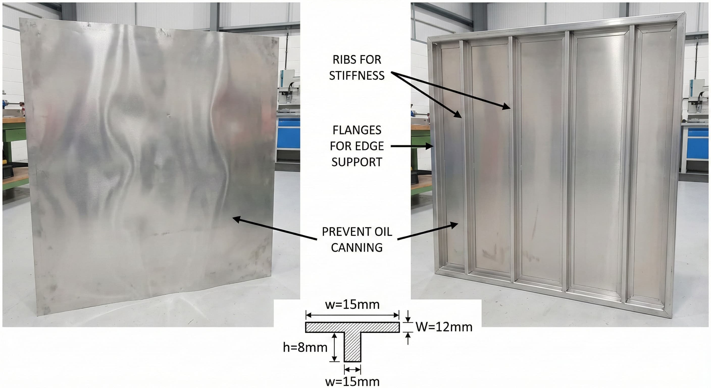
Oil canning—the unwanted flexural deformation of thin metal panels under load—represents one of the most persistent challenges in sheet metal fabrication. This structural instability manifests as visible waviness or buckling that compromises both aesthetic appeal and functional integrity of manufactured components.
Engineers at Microns Hub encounter oil canning issues across diverse applications, from architectural panels to electronic enclosures, where material thickness constraints conflict with rigidity requirements. The phenomenon occurs when panel dimensions exceed the material's natural stiffness threshold, typically when thickness-to-span ratios fall below critical values.
- Strategic rib placement can increase panel stiffness by 300-400% while adding minimal material cost
- Flange geometry optimization reduces oil canning susceptibility by distributing loads across reinforced perimeters
- Material selection between aluminum grades (6061-T6 vs 7075-T6) significantly impacts stiffening requirements and manufacturing costs
- Proper stiffener design eliminates post-manufacturing warping issues that plague thin-gauge fabrications
Understanding Oil Canning: The Engineering Physics
Oil canning occurs when applied forces exceed the local buckling strength of thin panels, creating elastic deformations that become visually apparent under normal viewing conditions. The critical buckling stress for rectangular panels follows the relationship:
σ_cr = k × π² × E × (t/b)²
Where k represents the buckling coefficient dependent on boundary conditions, E is the elastic modulus, t is panel thickness, and b is the unsupported width dimension. For aluminum 6061-T6 with E = 68.9 GPa, panels exceeding width-to-thickness ratios of 150:1 typically exhibit oil canning tendencies.
The visual threshold for oil canning detection ranges from 0.2-0.5 mm deflection amplitude, depending on surface finish and viewing angle. Anodized surfaces amplify the appearance of slight deformations due to light reflection patterns, while brushed finishes provide better camouflage for minor irregularities.
Material properties directly influence oil canning susceptibility. Aluminum alloys demonstrate varying resistance levels based on temper condition and composition:
| Alloy Grade | Yield Strength (MPa) | Elastic Modulus (GPa) | Oil Canning Resistance | Cost Factor |
|---|---|---|---|---|
| Al 6061-T6 | 276 | 68.9 | Good | 1.0x |
| Al 7075-T6 | 503 | 71.7 | Excellent | 2.2x |
| Al 5052-H32 | 193 | 70.3 | Fair | 0.9x |
| Steel 304 SS | 290 | 200 | Excellent | 1.8x |
Rib Design Fundamentals: Geometry and Placement Strategy
Effective rib design requires understanding the relationship between cross-sectional properties and bending resistance. The area moment of inertia increases proportionally to the height cubed, making tall, narrow ribs more efficient than wide, shallow ones for equivalent material usage.
Optimal rib spacing follows the rule of thirds for rectangular panels, with primary ribs positioned at 33% and 67% of the major dimension. This configuration minimizes maximum deflection while maintaining manufacturing efficiency. Secondary ribs, when required, should maintain spacing ratios between 1:2 and 1:3 relative to primary ribs.
Rib height calculations depend on panel loading conditions and stiffness requirements. For uniformly loaded panels, the minimum effective rib height equals:
h_min = t_panel × √(24 × L²/(E × t_panel × δ_max))
Where L represents the unsupported span and δ_max defines the acceptable deflection limit. Practical rib heights typically range from 3-15 mm for sheet metal applications, with 5-8 mm providing optimal stiffness-to-weight ratios.
Manufacturing considerations significantly influence rib design parameters. Precision CNC machining services enable complex rib profiles with tight tolerances, while brake forming limits rib complexity to simple geometric shapes. The choice between machined and formed ribs impacts both cost and performance characteristics.
Rib Profile Optimization
Cross-sectional rib profiles dramatically affect stiffening efficiency and manufacturing complexity. Common profiles include rectangular, triangular, and T-shaped configurations, each offering distinct advantages:
Rectangular ribs provide maximum material utilization and simple manufacturing but concentrate stress at sharp corners. Fillet radii of 0.5-1.0 mm eliminate stress concentrations while maintaining formability in thin materials.
Triangular ribs offer excellent stiffness-to-weight ratios and natural stress distribution but require specialized tooling for consistent formation. The included angle typically ranges from 60-90 degrees for optimal strength characteristics.
T-shaped ribs maximize second moment of area but necessitate complex forming sequences or machining operations. These profiles suit high-load applications where material usage optimization justifies increased manufacturing complexity.
Flange Engineering: Perimeter Reinforcement Strategies
Flange design represents the primary method for preventing edge-initiated oil canning while providing mounting interfaces and structural continuity. Effective flange geometry must balance stiffness enhancement with manufacturing constraints and assembly requirements.
Minimum flange width follows the relationship: W_flange ≥ 3 × t_material + bend radius, ensuring adequate material for reliable forming without cracking. For 2.0 mm aluminum 6061-T6, minimum flange widths of 8-10 mm provide sufficient stiffness enhancement while maintaining formability limits.
Flange stiffness contribution depends on the effective section modulus of the bent configuration. A 90-degree flange increases local stiffness by approximately 8-12 times compared to the flat panel equivalent, making flanges highly efficient stiffening elements.
The transition between panel and flange requires careful radius selection to prevent stress concentration while maintaining maximum stiffness transfer. Corner relief designs become critical at flange intersections, where material flow limitations can cause cracking or incomplete forming.
| Flange Configuration | Stiffness Multiplier | Forming Complexity | Material Utilization | Cost Impact |
|---|---|---|---|---|
| Simple 90° Bend | 8-10x | Low | 95% | +15% |
| Hemmed Edge | 12-15x | High | 85% | +35% |
| Return Flange | 6-8x | Medium | 90% | +25% |
| Compound Bend | 15-20x | Very High | 80% | +50% |
Flange-to-Panel Integration
The transition zone between panel and flange represents a critical design element that determines overall stiffening effectiveness. Sharp transitions create stress concentrations that can initiate fatigue failures, while overly gradual transitions reduce stiffness benefits.
Optimal bend radii for aluminum alloys range from 1.0-2.0 times material thickness, providing sufficient material flow while maintaining tight corner definition. Larger radii improve formability but reduce stiffness transfer efficiency, requiring careful balance based on application requirements.
Multi-step flange forming enables complex profiles that maximize stiffness while accommodating manufacturing limitations. Progressive die sequences can create compound flanges with variable heights and integrated mounting features, though tooling costs increase proportionally with complexity.
Material Selection Impact on Stiffener Performance
Material properties fundamentally determine stiffener effectiveness and manufacturing requirements. Elastic modulus, yield strength, and formability characteristics directly influence design parameters and cost optimization strategies.
Aluminum alloys dominate sheet metal applications due to excellent strength-to-weight ratios and corrosion resistance. However, different alloy compositions exhibit varying responses to stiffener integration:
6061-T6 aluminum provides optimal balance between formability and strength for most stiffening applications. The material readily accepts complex bend sequences while maintaining predictable spring-back characteristics. Work hardening during forming operations can increase local yield strength by 10-15% in high-strain regions.
7075-T6 aluminum offers superior strength characteristics but presents forming challenges due to reduced ductility. Stiffener designs must accommodate higher forming forces and potential cracking at sharp transitions. The material excels in applications where maximum strength-to-weight ratios justify increased manufacturing complexity.
5052-H32 aluminum demonstrates excellent formability but lower strength characteristics require increased stiffener dimensions for equivalent performance. This alloy suits applications prioritizing complex geometry over ultimate strength requirements.
Corrosion Considerations for Stiffened Panels
Stiffener integration creates geometric features that can trap moisture and accelerate corrosion processes, particularly in outdoor applications. Design strategies must address both material selection and protective coating requirements.
Galvanized steel alternatives provide enhanced corrosion resistance but require different forming parameters and stiffener design approaches due to coating thickness and brittleness considerations.
Drainage provisions become critical in ribbed panel designs, where horizontal surfaces can accumulate moisture. Incorporate drain holes with minimum 3 mm diameter at low points, positioned to prevent structural compromise while ensuring effective water evacuation.
Manufacturing Process Integration
Stiffener manufacturing methods significantly impact design feasibility, cost structures, and quality outcomes. The selection between forming, machining, and hybrid approaches depends on production volumes, tolerance requirements, and geometric complexity.
Press brake forming represents the most cost-effective approach for simple rib and flange geometries. Standard tooling accommodates bend radii from 0.5-6.0 mm with repeatability within ±0.1 mm. Complex multi-bend sequences require careful tool planning to avoid interference issues and maintain dimensional accuracy.
Progressive die forming enables high-volume production with integrated piercing, forming, and trimming operations. Initial tooling investments of €15,000-50,000 require production volumes exceeding 10,000 pieces for economic justification, but piece costs can drop to €0.50-2.00 depending on complexity.
CNC machining provides ultimate flexibility for prototype development and low-volume production. Complex rib profiles with varying heights and integrated mounting features are readily achievable, though material waste and cycle times limit economic viability to specialty applications.
| Manufacturing Method | Setup Cost (€) | Unit Cost Range (€) | Lead Time | Design Flexibility | Volume Threshold |
|---|---|---|---|---|---|
| Press Brake Forming | 200-500 | 2.50-8.00 | 3-5 days | Medium | 50-1000 pieces |
| Progressive Die | 15,000-50,000 | 0.50-2.00 | 6-8 weeks | High | 10,000+ pieces |
| CNC Machining | 100-300 | 8.00-25.00 | 1-2 days | Very High | 1-500 pieces |
| Hydroforming | 5,000-15,000 | 3.00-7.00 | 4-6 weeks | High | 1,000+ pieces |
Quality Control and Dimensional Verification
Stiffened panel inspection requires specialized measurement techniques to verify both geometric accuracy and structural performance. Coordinate measuring machines (CMM) provide precise dimensional verification but may require custom fixturing for complex geometries.
Flatness measurement becomes critical for panels with integrated stiffeners, where local deformations can propagate across unstiffened regions. Laser scanning systems enable rapid surface profiling with resolution to 0.01 mm, identifying potential oil canning issues before final assembly.
Load testing validates stiffener performance under service conditions. Simply supported beam testing with distributed loads simulates actual use conditions while providing quantitative deflection measurements for design verification.
For high-precision results, Get a quote in 24 hours from Microns Hub.
Cost Optimization Strategies
Stiffener cost optimization requires balancing material usage, manufacturing complexity, and performance requirements. Total cost includes raw materials, processing operations, tooling amortization, and quality verification activities.
Material utilization efficiency significantly impacts project economics. Nested layouts for laser cutting can achieve 85-95% material utilization, while complex die forming operations may waste 15-20% due to skeleton requirements and trim operations.
Stiffener standardization reduces tooling costs and improves manufacturing efficiency. Developing families of rib profiles and flange configurations enables tool reuse across multiple projects while maintaining design flexibility for specific applications.
Volume consolidation strategies can reduce unit costs by combining multiple part numbers into single production runs. However, inventory carrying costs and customer delivery requirements must be balanced against manufacturing economies of scale.
Design for Manufacturing Principles
DFM principles for stiffened panels focus on reducing manufacturing complexity while maintaining structural performance. Key considerations include bend sequence optimization, tool accessibility, and secondary operation minimization.
Bend sequence planning prevents tool interference and maintains dimensional accuracy throughout the forming process. Complex parts may require multiple setups with intermediate annealing operations to prevent work hardening and cracking.
Feature consolidation eliminates secondary operations by integrating mounting holes, slots, and other features into primary forming operations. This approach reduces handling costs and improves dimensional relationships between critical features.
Advanced Stiffening Techniques
Beyond traditional ribs and flanges, advanced stiffening techniques address specialized requirements for weight-critical applications, extreme load conditions, and aesthetic constraints.
Beaded stiffening creates linear reinforcement elements through controlled deformation without material addition. Bead profiles typically measure 2-5 mm in height with gradual transitions to minimize stress concentrations. This technique suits applications where protruding ribs interfere with assembly or aesthetic requirements.
Coined stiffening involves localized material displacement to create shallow reinforcement patterns. The process requires higher forming forces but produces virtually invisible stiffening elements ideal for appearance-critical applications. Coin depths of 0.3-0.8 mm provide measurable stiffness improvement while maintaining surface continuity.
Honeycomb core sandwich construction represents the ultimate stiffening approach for weight-critical applications. Aluminum honeycomb cores provide exceptional stiffness-to-weight ratios but require specialized bonding processes and environmental sealing considerations.
Integrated Design Approaches
Modern stiffening strategies integrate multiple reinforcement techniques to optimize performance while minimizing manufacturing complexity. Hybrid approaches combine ribs, flanges, and formed features in coordinated designs that maximize structural efficiency.
FEA optimization enables performance-based stiffener placement that minimizes material usage while meeting deflection criteria. Topology optimization algorithms can identify optimal reinforcement locations that may not be intuitive through traditional design approaches.
When ordering from Microns Hub, you benefit from direct manufacturer relationships that ensure superior quality control and competitive pricing compared to marketplace platforms. Our technical expertise and personalized service approach means every project receives the attention to detail it deserves, from initial design consultation through final quality verification.
Additive manufacturing techniques enable complex internal stiffening geometries impossible through conventional forming methods. 3D-printed stiffening elements can be integrated with traditional sheet metal components to create hybrid structures with optimized performance characteristics.
Performance Validation and Testing
Stiffened panel performance validation requires comprehensive testing protocols that verify both immediate structural performance and long-term durability characteristics. Testing methodologies must simulate actual service conditions while providing quantitative data for design optimization.
Static load testing provides baseline stiffness measurements under controlled conditions. Three-point and four-point bending tests quantify load-deflection relationships while identifying failure modes and ultimate capacity limits. Test fixtures must accommodate various panel geometries while maintaining consistent boundary conditions.
Dynamic testing evaluates stiffened panel response to vibration and impact loading. Modal analysis identifies natural frequencies and mode shapes that could lead to resonance issues in service environments. Impact testing validates damage resistance and energy absorption characteristics for transportation and handling scenarios.
Fatigue testing becomes critical for stiffened panels subject to cyclic loading conditions. S-N curve development for specific stiffener configurations enables service life prediction and maintenance scheduling optimization. Test parameters must reflect actual load spectra and environmental conditions expected in service.
Through our manufacturing services, we ensure every stiffened panel meets or exceeds specified performance criteria through rigorous testing and quality assurance protocols.
Frequently Asked Questions
What thickness-to-span ratio typically requires stiffening to prevent oil canning?
Panels with thickness-to-span ratios below 1:150 generally require stiffening for aluminum alloys. For example, a 300 mm wide panel should be at least 2.0 mm thick to avoid oil canning, or incorporate ribs/flanges if thinner material is necessary. Steel panels can tolerate ratios up to 1:200 due to higher elastic modulus.
How much stiffness improvement can ribs provide compared to flat panels?
Properly designed ribs can increase panel stiffness by 300-400% while adding only 10-15% material cost. A 5 mm high rib in 2.0 mm aluminum can provide equivalent stiffness to a 4.5 mm solid panel, representing significant weight and cost savings in large panel applications.
What is the minimum flange width needed for effective stiffening?
Minimum effective flange width equals 3 times material thickness plus bend radius. For 2.0 mm aluminum with 2.0 mm bend radius, minimum flange width is 8.0 mm. However, 10-15 mm widths provide better stiffness enhancement and easier manufacturing tolerances.
Can stiffeners be added to existing panels without complete redesign?
Yes, retrofit stiffening is possible through adhesive bonding or mechanical attachment of external ribs. Structural adhesives like 3M VHB or Loctite structural acrylics can bond aluminum stiffeners with strengths exceeding 15 MPa. However, integrated design approaches typically provide better performance and aesthetics.
How do environmental conditions affect stiffener design requirements?
Temperature variations cause differential expansion that can stress stiffener attachments. Design expansion joints or flexible connections for temperature ranges exceeding 50°C. Outdoor applications require drainage provisions and corrosion protection. UV exposure can degrade adhesive bonds, requiring mechanical backup systems.
What manufacturing tolerances are achievable for ribbed panels?
Press brake forming maintains ±0.1 mm dimensional tolerance for simple rib geometries. Progressive die operations achieve ±0.05 mm repeatability but require higher tooling investment. CNC machined ribs can hold ±0.02 mm but cost 3-4 times more than formed alternatives.
How does material grain direction affect stiffener performance?
Bending parallel to grain direction (with the grain) provides 10-15% better formability but slightly reduced strength perpendicular to the bend axis. For maximum stiffness, orient ribs perpendicular to the rolling direction when possible. Cross-grain bending requires larger bend radii to prevent cracking but provides isotropic strength characteristics.
MICRONS HUB DV Ε.Ε. · VAT: EL803129638 · GEMI: 190254227000 · Industrial Area, Street B, Number 4, 71601 Heraklion, Crete, Greece