Corner Relief Designs: Rectangular vs. Circular Reliefs for Clean Bends
Corner relief design represents one of the most critical decisions in sheet metal fabrication, directly impacting bend quality, tool life, and production efficiency. The choice between rectangular and circular corner reliefs determines not only the aesthetic finish but also the structural integrity and manufacturability of bent components.
Key Takeaways:
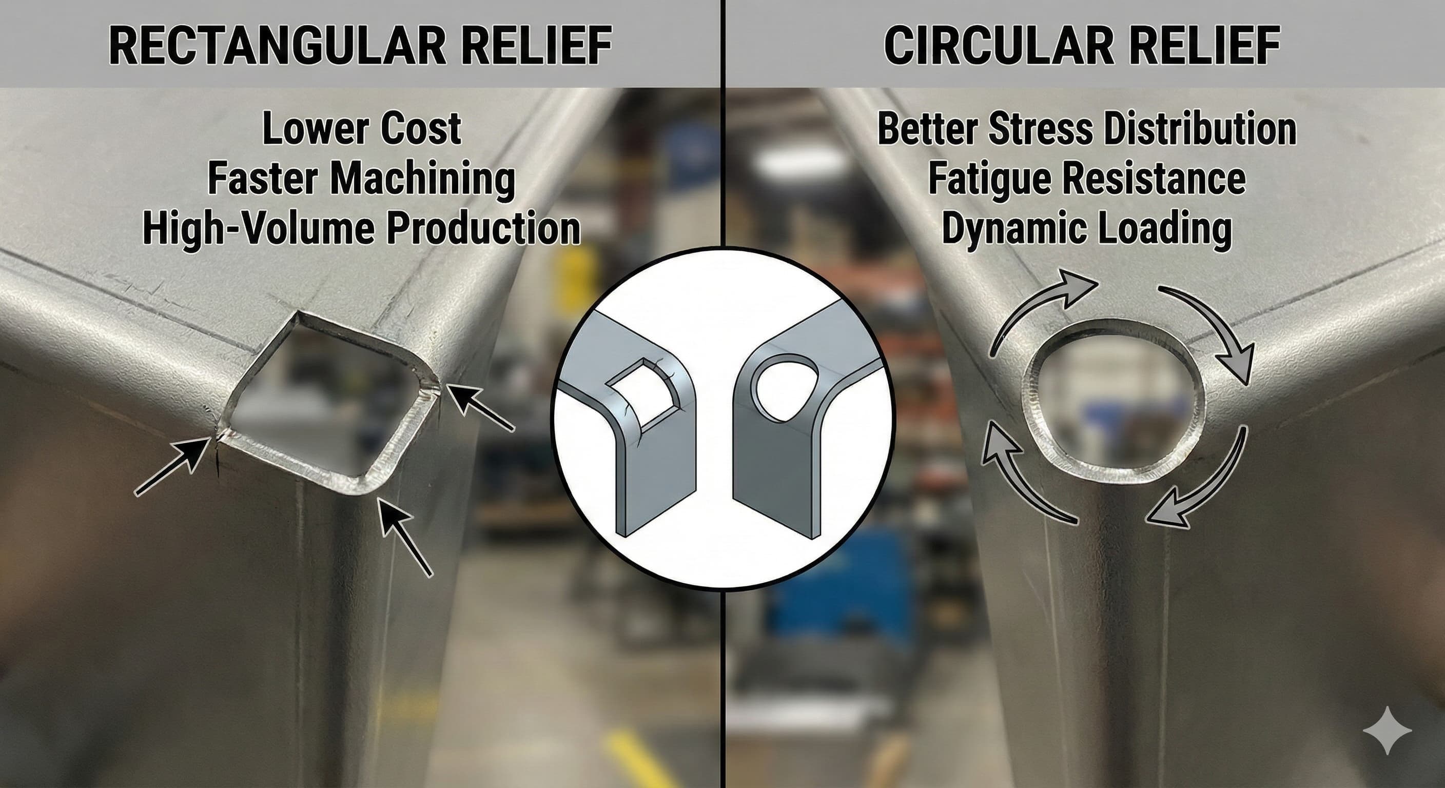
- Rectangular reliefs offer superior material economy and faster machining times, making them ideal for high-volume production
- Circular reliefs provide better stress distribution and fatigue resistance, crucial for dynamic loading applications
- Relief dimensions must follow ISO 2768 guidelines, with typical depths ranging from 0.5mm to 2.0mm depending on material thickness
- Proper relief design can reduce corner cracking by up to 85% in materials like Al 6061-T6 and stainless steel 304
Understanding Corner Relief Fundamentals
Corner reliefs serve as stress concentration management features in sheet metal designs, preventing material buildup and cracking during the bending process. When two bend lines intersect, the overlapping material creates a geometric impossibility that must be resolved through strategic material removal.
The physics behind corner relief necessity stems from the fundamental behavior of metal during plastic deformation. As sheet metal bends, the outer fibers experience tensile stress while inner fibers compress. At corner intersections, this stress pattern becomes complex, creating multi-directional forces that can exceed the material's ultimate tensile strength.
ISO 2768 standards specify minimum relief dimensions based on material thickness and bend radius relationships. For materials with thickness (t) between 0.5mm and 3.0mm, the relief depth should equal 1.5t + bend radius, while the relief width must accommodate the bend allowance calculations to prevent interference.
Material properties significantly influence relief design requirements. High-strength alloys like Al 7075-T6 demand larger relief dimensions compared to softer materials such as Al 1100-H14, due to their reduced ductility and higher elastic modulus values.
Rectangular Corner Relief Design
Rectangular reliefs represent the most economical and widely-adopted corner relief solution in industrial sheet metal fabrication services. Their geometric simplicity translates directly into manufacturing advantages, particularly for high-volume production environments.
The rectangular relief design consists of two perpendicular cuts intersecting at 90 degrees, creating a square or rectangular void at the corner intersection. Standard dimensions follow the formula: Length (L) = 1.5t + R + 0.5mm, Width (W) = 1.5t + R + 0.5mm, where t represents material thickness and R denotes bend radius.
Manufacturing advantages of rectangular reliefs include simplified programming for CNC punching operations, reduced tool wear due to straight-line cutting paths, and faster cycle times compared to curved geometries. Turret punch presses can execute rectangular reliefs using standard rectangular punches, eliminating the need for specialized tooling.
From a structural perspective, rectangular reliefs provide adequate stress relief for most applications, particularly those involving static loading conditions. The sharp corners do create localized stress concentrations, but these typically remain within acceptable limits for standard industrial applications.
| Material Thickness | Recommended Length (mm) | Recommended Width (mm) | Typical Tolerance (±mm) |
|---|---|---|---|
| 0.5mm | 2.0 | 2.0 | 0.05 |
| 1.0mm | 3.5 | 3.5 | 0.08 |
| 1.5mm | 4.75 | 4.75 | 0.10 |
| 2.0mm | 6.0 | 6.0 | 0.13 |
| 3.0mm | 8.5 | 8.5 | 0.15 |
Cost analysis reveals rectangular reliefs typically cost 15-25% less than circular alternatives due to reduced machining time and standard tooling requirements. For production runs exceeding 1,000 pieces, this cost differential becomes significant, often justifying the selection of rectangular reliefs even in applications where circular designs might offer marginal technical advantages.
Circular Corner Relief Design
Circular corner reliefs offer superior stress distribution characteristics, making them the preferred choice for applications involving dynamic loading, vibration, or fatigue concerns. The curved geometry eliminates sharp stress concentration points inherent in rectangular designs.
The circular relief design utilizes a single radius cut, typically ranging from 2.0mm to 6.0mm depending on material thickness and application requirements. The radius calculation follows: R = 1.2 × (material thickness + bend radius) + 1.0mm, ensuring adequate clearance while optimizing stress flow patterns.
Stress analysis using finite element methods demonstrates that circular reliefs reduce peak stress concentrations by 35-45% compared to rectangular alternatives. This improvement becomes critical in aerospace, automotive, and medical device applications where component reliability directly impacts safety.
Manufacturing circular reliefs requires specialized tooling or additional machining operations. CNC turret punches need circular punches in various diameters, while laser cutting systems can produce any radius without tooling constraints. This flexibility makes laser cutting particularly attractive for prototyping and small-batch production.
For high-precision results, Get your custom quote delivered in 24 hours from Microns Hub.
The material removal volume in circular reliefs typically exceeds rectangular designs by 20-30%, representing a minor material cost increase but potentially significant improvement in component longevity. This trade-off proves worthwhile in applications where replacement costs exceed initial manufacturing premiums.
Comparative Analysis: Performance Characteristics
Fatigue testing reveals significant performance differences between rectangular and circular relief designs. Components with circular reliefs demonstrate 40-60% longer fatigue life under cyclic loading conditions, particularly important in automotive suspension components and aerospace structures.
Stress concentration factors (Kt) provide quantitative comparison metrics. Rectangular reliefs typically exhibit Kt values between 2.8-3.2, while circular reliefs achieve Kt values of 1.8-2.1. Lower Kt values indicate more uniform stress distribution and reduced failure probability.
| Performance Metric | Rectangular Relief | Circular Relief | Improvement Factor |
|---|---|---|---|
| Stress Concentration (Kt) | 2.8-3.2 | 1.8-2.1 | 35-45% reduction |
| Fatigue Life (cycles) | 50,000-80,000 | 85,000-130,000 | 60-70% increase |
| Manufacturing Time (sec) | 2.5-3.0 | 3.5-4.5 | 40% increase |
| Tool Life (hits) | 100,000-150,000 | 80,000-120,000 | 20% reduction |
| Material Usage (%) | 98.5-99.0 | 97.5-98.0 | 1-1.5% increase |
Surface finish considerations also favor circular reliefs, particularly in visible applications. The smooth curved geometry eliminates sharp edges that can snag during handling or assembly, reducing the risk of cuts and improving overall safety.
Material-Specific Considerations
Different materials respond uniquely to corner relief designs, requiring customized approaches for optimal results. Aluminum alloys, stainless steels, and mild steels each present distinct challenges and opportunities.
Aluminum 6061-T6 exhibits excellent ductility, allowing both rectangular and circular reliefs to perform adequately. However, the material's tendency toward work hardening makes circular reliefs preferable for applications involving repeated bending or forming operations. The reduced stress concentrations help maintain ductility throughout the manufacturing process.
Stainless steel 304 presents greater challenges due to its work-hardening characteristics and higher strength. Circular reliefs become particularly important, as the improved stress distribution helps prevent micro-cracking that can propagate over time. The relief dimensions should increase by 20-25% compared to aluminum applications to accommodate the material's reduced ductility.
High-strength steels require careful consideration of relief design, as their limited ductility makes them susceptible to cracking. Circular reliefs with generous radii often become mandatory, despite the increased manufacturing complexity and cost.
Manufacturing Process Integration
Relief design must integrate seamlessly with overall manufacturing workflows to optimize efficiency and quality. The choice between rectangular and circular reliefs affects tooling selection, programming complexity, and production sequencing.
CNC turret punch operations favor rectangular reliefs due to standard tooling availability and simple programming requirements. The linear tool paths reduce cycle time and extend tool life, particularly important for high-volume production runs. However, modern turret punches can accommodate circular punches, though this requires additional tooling investment.
Laser cutting systems offer greater flexibility, capable of producing any relief geometry without tooling constraints. This advantage makes laser cutting attractive for prototyping and low-volume production, where tooling amortization becomes prohibitive. The precision achievable with laser systems also enables complex relief geometries combining rectangular and circular features.
When ordering from Microns Hub, you benefit from direct manufacturer relationships that ensure superior quality control and competitive pricing compared to marketplace platforms. Our technical expertise and comprehensive our manufacturing services approach means every project receives the attention to detail it deserves, whether you require simple rectangular reliefs or complex curved geometries.
Integration with tab and slot construction requires careful coordination of relief placement and dimensions. The reliefs must provide adequate clearance for assembly operations while maintaining structural integrity at joint locations.
Quality Control and Inspection
Corner relief quality directly impacts final component performance, making rigorous inspection protocols essential. Dimensional accuracy, edge quality, and geometric consistency all require verification to ensure specification compliance.
Dimensional inspection focuses on relief depth, width, and positional accuracy relative to bend lines. Coordinate measuring machines (CMM) provide the precision necessary for critical applications, though simpler go/no-go gauges suffice for many production environments.
Edge quality assessment examines surface roughness, burr formation, and micro-cracking potential. Rectangular reliefs typically exhibit superior edge quality due to the punching process's clean shearing action, while laser-cut circular reliefs may require secondary deburring operations.
Statistical process control (SPC) implementation helps maintain consistent relief quality throughout production runs. Key parameters include relief dimensions, edge roughness, and positional accuracy, with control limits established based on component criticality and end-use requirements.
Cost Optimization Strategies
Cost optimization requires balancing initial manufacturing expenses against long-term component performance and replacement costs. This analysis becomes particularly important for high-volume applications where small unit cost differences aggregate into significant totals.
Direct manufacturing costs favor rectangular reliefs, with typical savings of €0.05-0.15 per component compared to circular alternatives. These savings stem from reduced cycle time, standard tooling usage, and simplified programming requirements. For production volumes exceeding 10,000 pieces annually, rectangular reliefs often provide compelling economic advantages.
However, lifecycle cost analysis may favor circular reliefs in applications where improved fatigue resistance reduces maintenance and replacement frequency. The premium paid for circular relief manufacturing often proves worthwhile when replacement costs, downtime expenses, and safety considerations factor into the total cost equation.
| Production Volume | Rectangular Cost (€/piece) | Circular Cost (€/piece) | Break-even Analysis |
|---|---|---|---|
| 100-500 pieces | 0.45-0.38 | 0.52-0.45 | Rectangular preferred |
| 500-2,000 pieces | 0.35-0.28 | 0.42-0.35 | Application dependent |
| 2,000-10,000 pieces | 0.25-0.20 | 0.32-0.26 | Consider lifecycle costs |
| 10,000+ pieces | 0.18-0.15 | 0.25-0.20 | Rectangular strongly favored |
Advanced Design Techniques
Modern corner relief design extends beyond simple rectangular or circular geometries, incorporating hybrid approaches that optimize specific performance characteristics. These advanced techniques require sophisticated manufacturing capabilities but can deliver superior results for demanding applications.
Teardrop reliefs combine rectangular and circular features, utilizing straight sides for manufacturing efficiency while incorporating radiused ends for stress reduction. This hybrid approach achieves 70-80% of circular relief stress benefits while maintaining 85-90% of rectangular relief manufacturing efficiency.
Variable-radius reliefs adapt circular geometry to accommodate different stress patterns within the same component. Finite element analysis guides radius optimization, creating relief geometries tailored to specific loading conditions and material properties.
Multi-stage reliefs incorporate different geometries at various depths, providing optimal stress distribution while minimizing material removal. These complex geometries require advanced manufacturing capabilities but can achieve performance improvements exceeding single-geometry approaches.
Frequently Asked Questions
What factors determine the choice between rectangular and circular corner reliefs?
The selection depends on application requirements, production volume, and material properties. Rectangular reliefs suit high-volume production with standard tooling, while circular reliefs excel in fatigue-critical applications requiring superior stress distribution. Material thickness, bend radius, and loading conditions all influence the optimal choice.
How do corner relief dimensions scale with material thickness?
Relief dimensions typically follow the formula: Relief size = 1.5 × material thickness + bend radius + 0.5mm clearance. Thicker materials require proportionally larger reliefs to accommodate increased material flow during bending. High-strength materials may require 20-25% larger reliefs compared to standard calculations.
Can corner reliefs be added after initial fabrication?
While technically possible, post-fabrication relief addition proves challenging and expensive. Secondary machining operations introduce setup costs and potential quality issues. Optimal results require relief incorporation during initial fabrication planning, ensuring proper integration with manufacturing workflows and quality control processes.
What inspection methods verify corner relief quality?
Quality verification employs dimensional inspection using CMM systems or go/no-go gauges, visual examination for edge quality and burr formation, and functional testing for critical applications. Statistical process control monitors relief consistency throughout production runs, with control limits based on component criticality.
How do corner reliefs affect overall component strength?
Properly designed reliefs improve component strength by preventing stress concentrations that could initiate cracking. While reliefs remove material, the stress distribution improvement typically outweighs material reduction effects. Circular reliefs provide 35-45% better stress distribution compared to rectangular alternatives.
What manufacturing processes work best for each relief type?
Rectangular reliefs optimize for CNC punching operations using standard tooling, while circular reliefs suit laser cutting systems offering geometric flexibility. Waterjet cutting accommodates both geometries effectively, though at higher cost. Process selection depends on production volume, precision requirements, and available equipment.
Are there industry-specific preferences for relief types?
Aerospace and medical industries typically prefer circular reliefs for superior fatigue resistance and stress distribution. Automotive applications vary based on component function, with structural elements favoring circular reliefs while cosmetic parts often use rectangular alternatives. Electronics enclosures commonly employ rectangular reliefs for cost efficiency and EMI shielding continuity.
MICRONS HUB DV Ε.Ε. · VAT: EL803129638 · GEMI: 190254227000 · Industrial Area, Street B, Number 4, 71601 Heraklion, Crete, Greece