K-Factor Explained: Calculating Bend Allowances for Precision Sheet Metal
Sheet metal fabricators working with tolerances tighter than ±0,25 mm face a fundamental challenge: achieving precise bend dimensions while accounting for material deformation during the bending process. The K-factor serves as the mathematical bridge between flat pattern development and final bent geometry, determining whether parts meet critical assembly requirements or become costly scrap.
Understanding K-factor calculation becomes essential when designing brackets, enclosures, and structural components where bend accuracy directly impacts fit and function. This comprehensive guide examines the engineering principles, calculation methods, and practical applications that define precision sheet metal fabrication.
- K-factor represents the ratio of neutral axis position to material thickness, typically ranging from 0,25 to 0,50 for common sheet metals
- Accurate bend allowance calculations require consideration of material properties, tooling geometry, and forming parameters
- Precision applications demand empirical K-factor validation through test bends and measurement verification
- Advanced CAD systems integrate K-factor databases for automated flat pattern development
Understanding K-Factor Fundamentals in Sheet Metal Bending
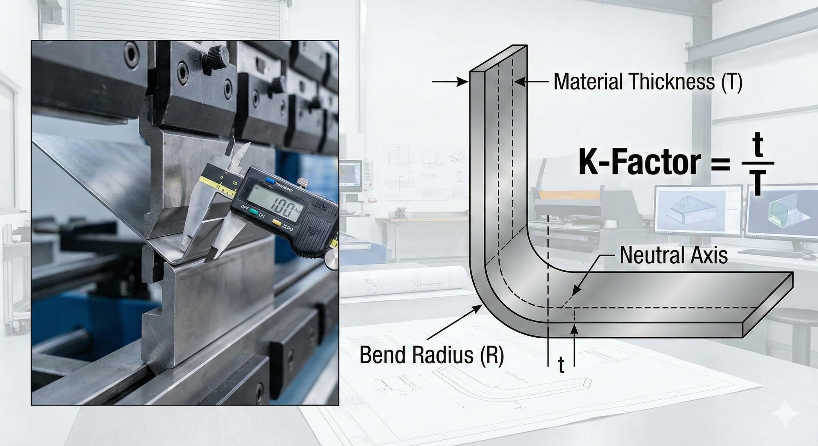
The K-factor quantifies the relationship between a material's neutral axis and its thickness during the bending process. When sheet metal undergoes bending, the outer surface stretches while the inner surface compresses, creating a neutral axis where material length remains constant. This neutral axis position determines the bend allowance required for accurate flat pattern development.
Mathematically, the K-factor equals the distance from the inner bend radius to the neutral axis, divided by the material thickness. For a part with 2,0 mm thickness and neutral axis positioned 0,8 mm from the inner surface, the K-factor calculates to 0,40. This dimensionless value remains relatively consistent for specific material-tooling combinations.
Material properties significantly influence K-factor values. Ductile materials like aluminum 1100-O exhibit higher K-factors (0,45-0,50) due to greater material flow during forming. Conversely, harder materials such as stainless steel 304 typically demonstrate lower K-factors (0,30-0,40) because of reduced deformation characteristics.
Tooling geometry also affects K-factor determination. Smaller punch radii create sharper bends with lower K-factors, while larger radii promote gradual forming with higher values. The relationship between punch radius and material thickness, expressed as the R/T ratio, provides preliminary K-factor estimation guidance.
Material GradeTypical K-Factor RangeTensile Strength (MPa)Forming CharacteristicsAluminum 1100-O0,45 - 0,5090 - 165Excellent formability, high ductilityAluminum 6061-T60,35 - 0,42310 - 380Good formability, moderate strengthSteel 1008/10100,40 - 0,45320 - 420Good formability, low carbon contentStainless 3040,30 - 0,40515 - 620Moderate formability, work hardeningStainless 3160,32 - 0,42515 - 670Better formability than 304 Bend Allowance Calculation Methods and Formulas
Bend allowance represents the arc length of the neutral axis through the bend zone, providing the critical dimension for flat pattern development. The fundamental formula incorporates the bend angle, inside radius, material thickness, and K-factor: BA = (π/180) × (R + K × T) × A, where BA equals bend allowance, R represents inside radius, K denotes the K-factor, T indicates material thickness, and A specifies the bend angle in degrees.
For a 90-degree bend in 1,5 mm aluminum 6061-T6 with 3,0 mm inside radius and K-factor of 0,38, the calculation yields: BA = (π/180) × (3,0 + 0,38 × 1,5) × 90 = 9,42 + 0,90 = 10,32 mm. This bend allowance value determines the arc length to include in the flat pattern development.
The bend deduction method offers an alternative approach, calculating the material length difference between the bent and unbent states. Bend deduction equals 2 × (outside setback) - bend allowance, where outside setback represents the distance from the bend line to the outside surface. This method proves particularly useful for CAD systems and automated nesting software.
Advanced applications may require bend allowance correction factors to account for springback, tool wear, and material variations. These correction factors, typically ranging from 0,95 to 1,05, fine-tune theoretical calculations based on empirical testing and production experience.
Multi-bend calculations require careful consideration of bend sequence and intermediate flat lengths. Each bend contributes its individual allowance while maintaining overall part dimensions. Complex geometries with multiple bends, returns, and offsets demand systematic calculation approaches to prevent cumulative errors.
Material Property Influence on K-Factor Selection
Material grain structure significantly impacts K-factor determination and bending behavior. Cold-rolled materials exhibit directional properties with different K-factors parallel and perpendicular to the rolling direction. Aluminum 6061-T6 may demonstrate a K-factor of 0,38 parallel to grain and 0,42 perpendicular, requiring orientation-specific calculations for critical applications.
Work hardening characteristics affect K-factor stability during forming operations. Materials with high work hardening rates, such as stainless steel 301, may exhibit K-factor variations depending on bend severity and forming speed. Progressive hardening reduces material flow, effectively lowering K-factors as bending progresses.
Surface conditions and material finish influence bending behavior through friction effects and stress concentration. Mill finish materials typically provide consistent K-factor performance, while coated or textured surfaces may require adjustment factors. Pre-painted steel often exhibits slightly higher K-factors due to coating lubrication effects.
Thickness variations within standard tolerances can affect K-factor accuracy in precision applications. Materials specified as 2,0 mm ±0,1 mm may demonstrate K-factor variations of ±0,02, potentially impacting final part dimensions by 0,05 mm or more in critical bend zones.
For high-precision results, Request a free quote and get pricing in 24 hours from Microns Hub.
Thickness Range (mm)Aluminum 6061-T6 K-FactorSteel 1008 K-FactorStainless 304 K-Factor0,5 - 1,00,33 - 0,380,35 - 0,420,27 - 0,331,0 - 2,00,36 - 0,410,38 - 0,440,30 - 0,372,0 - 3,00,38 - 0,430,40 - 0,460,32 - 0,393,0 - 5,00,40 - 0,450,42 - 0,480,34 - 0,41 Tooling Effects and Press Brake Considerations
Punch nose radius directly influences K-factor values through its effect on bend formation. Sharp punches with small radii concentrate stress and reduce material flow, resulting in lower K-factors. Conversely, larger punch radii promote gradual forming with higher K-factors and improved surface quality.
Die opening width affects material support during bending, influencing stress distribution and neutral axis position. Standard practice recommends die openings of 8 to 12 times material thickness, with wider openings promoting higher K-factors. Narrow dies may cause bottoming effects that artificially reduce calculated K-factors.
Bottoming versus air bending techniques produce different K-factor characteristics. Air bending allows natural material flow with consistent K-factors across various angles, while bottoming creates controlled deformation that may require angle-specific K-factor adjustments. Coining operations typically exhibit the lowest K-factors due to material compression effects.
Press brake tonnage and forming speed influence material flow during bending operations. Insufficient tonnage may result in incomplete forming with inconsistent K-factors, while excessive force can cause material thinning and altered neutral axis positions. Optimal forming speeds allow proper material flow without inducing stress concentrations.
Tool wear affects bending consistency over production runs. Worn punches may create slightly different bend radii, altering K-factor calculations. Regular tool inspection and replacement schedules maintain K-factor consistency for precision applications requiring precision CNC machining services integration.
Empirical K-Factor Determination and Testing Methods
Theoretical K-factors provide starting points for bend calculations, but precision applications require empirical validation through systematic testing. Test bend procedures involve forming sample parts with known dimensions, measuring actual bend results, and calculating effective K-factors from observed geometry.
The standard test procedure begins with preparing test strips of production material, typically 150 mm long by 25 mm wide. Mark precise bend lines 50 mm from each end, ensuring accurate measurement references. Form 90-degree bends using production tooling and settings, maintaining consistent forming parameters.
Measurement techniques require precision instruments capable of 0,01 mm resolution. Measure the inside radius using radius gauges or optical measurement systems, and verify bend angles with precision protractors or coordinate measuring machines. Calculate the effective K-factor by working backward from measured dimensions to theoretical requirements.
Multiple test samples provide statistical validation of K-factor consistency. Minimum sample sizes of 5 pieces per material-tooling combination establish reliable average values and variation ranges. Document environmental conditions, material lot numbers, and tooling identification for traceability.
Production validation involves forming representative parts and measuring critical dimensions against design requirements. Parts requiring tab and slot construction demand particular attention to bend accuracy for proper fit-up.
Advanced K-Factor Applications in CAD/CAM Systems
Modern CAD systems integrate comprehensive K-factor databases for automated flat pattern development. These databases contain empirically validated values for common material-tooling combinations, reducing design time and improving accuracy. Leading software packages allow custom K-factor entry for specialized applications.
Parametric design approaches link K-factors to material properties and forming parameters, enabling automatic updates when design changes occur. Feature-based modeling systems recognize bend features and apply appropriate K-factors based on material selection and tooling specifications.
CAM integration extends K-factor applications to manufacturing planning and quality control. CNC press brake programming uses K-factor data for automatic bend sequence optimization and tool selection. Real-time angle correction systems adjust forming parameters based on K-factor predictions and measurement feedback.
Simulation software incorporates finite element analysis with K-factor validation for complex forming operations. These tools predict material behavior, stress distribution, and final geometry before physical prototyping. Advanced simulations account for material anisotropy, work hardening, and tool-part interactions.
Data management systems track K-factor performance across production runs, identifying trends and optimization opportunities. Statistical process control applications monitor bend accuracy and adjust K-factors for continuous improvement. Integration with our manufacturing services ensures consistent quality control throughout the production process.
Quality Control and Measurement Verification
Precision sheet metal applications demand rigorous quality control procedures to verify K-factor accuracy and bend conformance. Statistical sampling plans based on ISO 2859-1 provide systematic inspection approaches for production validation. Critical applications may require 100% inspection with automated measurement systems.
Coordinate measuring machines (CMMs) offer the highest accuracy for bend verification, with measurement uncertainties below ±0,005 mm. Optical measurement systems provide rapid inspection capabilities for production environments, combining speed with sufficient accuracy for most applications. Portable measurement tools enable in-process verification and rapid feedback.
Measurement uncertainty analysis accounts for instrument limitations, part variations, and environmental effects. Type A uncertainties from statistical analysis of repeated measurements combine with Type B uncertainties from instrument specifications to determine overall measurement confidence. Precision applications require uncertainty budgets to ensure measurement capability exceeds required tolerances.
Process capability studies evaluate K-factor consistency over extended production runs. Cp and Cpk calculations quantify process performance relative to specification limits, identifying improvement opportunities. Control charts monitor key parameters and detect process drift before quality issues develop.
When ordering from Microns Hub, you benefit from direct manufacturer relationships that ensure superior quality control and competitive pricing compared to marketplace platforms. Our technical expertise and personalized service approach means every project receives the attention to detail it deserves, with comprehensive quality documentation and traceability throughout the production process.
Measurement MethodAccuracy (mm)SpeedBest ApplicationCMM±0,002SlowCritical dimensions, calibrationOptical Scanner±0,010FastProduction inspectionRadius Gauges±0,025FastShop floor verificationCalipers±0,020FastBasic dimensional checks Cost Optimization Through Accurate K-Factor Application
Accurate K-factor determination reduces material waste through precise flat pattern development. Overestimated bend allowances create excess material consumption, while underestimated values lead to short parts requiring rework or scrap. A 2% improvement in K-factor accuracy can reduce material usage by 1-3% in complex parts with multiple bends.
Production efficiency gains result from reduced setup time and fewer iterative adjustments. Accurate K-factors minimize trial-and-error approaches, enabling first-article success and faster production ramp-up. Time savings in prototype development and production setup provide significant cost advantages in competitive markets.
Tooling optimization through K-factor analysis identifies the most efficient punch and die combinations for specific applications. Standardizing on proven tool sets with validated K-factors reduces inventory requirements and improves consistency. Tool life improvements result from optimized forming parameters and reduced over-forming.
Quality cost reduction through defect prevention provides the largest economic impact. Scrap rates below 1% become achievable with properly validated K-factors, compared to 5-10% rates with theoretical values alone. Reduced inspection requirements and warranty claims further improve profitability.
Supply chain advantages emerge from consistent part quality and reliable delivery schedules. Customers value suppliers who demonstrate process control and predictable outcomes. Long-term partnerships develop when precision requirements are consistently met through proper K-factor application.
Industry-Specific K-Factor Requirements
Aerospace applications demand the highest levels of K-factor validation and documentation. AS9100 quality systems require full traceability of forming parameters and empirical validation for flight-critical components. Material certifications, tooling records, and process parameters must demonstrate statistical control for regulatory compliance.
Medical device manufacturing requires K-factor validation under FDA quality system regulations. Biocompatible materials such as titanium Grade 2 and stainless steel 316L demand specific K-factor determination due to their unique forming characteristics. Process validation includes worst-case analysis and design margin verification.
Automotive applications focus on high-volume consistency and cost optimization. Statistical process control systems monitor K-factor performance across millions of parts, identifying subtle trends and optimization opportunities. Supplier quality agreements specify K-factor validation requirements and ongoing monitoring protocols.
Electronics enclosures require precise K-factors for EMI shielding effectiveness and component fit. Thin materials (0,5-1,0 mm) with tight bend tolerances challenge traditional K-factor approaches. Special consideration for PEM fasteners integration requires coordinated design approaches.
Architecture and construction applications emphasize weather sealing and thermal expansion accommodation. Large panel forming with multiple bends requires careful K-factor validation to prevent cumulative errors. Field assembly considerations influence design approaches and tolerance allocation strategies.
Frequently Asked Questions
What K-factor should I use for 2mm aluminum 6061-T6?
For 2mm aluminum 6061-T6, start with a K-factor of 0,38-0,40 for air bending operations. The exact value depends on your punch radius, die opening, and forming speed. Validate this initial estimate through test bends using your actual tooling and production parameters to achieve optimal accuracy.
How does punch radius affect K-factor calculations?
Smaller punch radii create sharper bends with lower K-factors (0,25-0,35), while larger radii promote gradual forming with higher K-factors (0,40-0,50). The relationship follows the R/T ratio - radius divided by thickness. Maintain punch radius at least equal to material thickness for consistent results and avoid cracking.
Can I use the same K-factor for different bend angles?
Air bending maintains relatively consistent K-factors across different angles (30-135 degrees), making this the preferred method for variable geometry parts. Bottoming and coining operations may require angle-specific K-factors due to different material flow characteristics. Always validate critical angles through test parts.
Why do my calculated dimensions not match actual bent parts?
Dimensional discrepancies typically result from using theoretical K-factors instead of empirically validated values, springback effects not accounted for in calculations, or inconsistent tooling setup. Measure your actual inside radii and bend angles, then calculate effective K-factors from real parts to improve accuracy.
How often should I verify K-factors in production?
Verify K-factors monthly for high-volume production, or after any tooling changes, material lot changes, or equipment maintenance. Critical applications may require daily verification through statistical sampling. Maintain control charts to identify trends and prevent quality issues before they occur.
What measurement accuracy is required for K-factor validation?
K-factor validation requires measurement uncertainty at least 10 times better than your final tolerance requirements. For parts with ±0,1mm bend tolerances, use instruments with ±0,01mm accuracy or better. CMMs provide the highest accuracy, while optical scanners offer good compromise between speed and precision for production environments.
How do I handle K-factors for custom alloys or exotic materials?
Custom alloys require empirical K-factor determination through systematic testing. Start with values for similar base materials, then conduct bend tests across your typical thickness and radius range. Document material properties including tensile strength, elongation, and work hardening characteristics to predict K-factor behavior and establish process windows.
MICRONS HUB DV Ε.Ε. · VAT: EL803129638 · GEMI: 190254227000 · Industrial Area, Street B, Number 4, 71601 Heraklion, Crete, Greece