PEM Fasteners: Selecting the Right Press-Fit Nuts for Thin Aluminum
Securing thin aluminum panels presents unique challenges that standard threaded fasteners cannot address effectively. When dealing with material thicknesses below 2 mm, traditional nuts and bolts create stress concentrations that compromise structural integrity, while tapped threads often strip under moderate loads. PEM press-fit nuts solve this critical engineering problem by distributing loads across a larger surface area and creating permanent, reliable threaded connections in thin sheet metal assemblies.
Key Takeaways
- Press-fit nuts distribute loads more effectively than tapped threads in aluminum sheets under 2 mm thick
- Self-clinching fasteners eliminate the need for secondary operations and provide flush mounting capabilities
- Material selection between stainless steel and aluminum PEM nuts directly impacts galvanic corrosion resistance
- Proper hole sizing within ±0.05 mm tolerances ensures optimal grip strength and prevents panel distortion
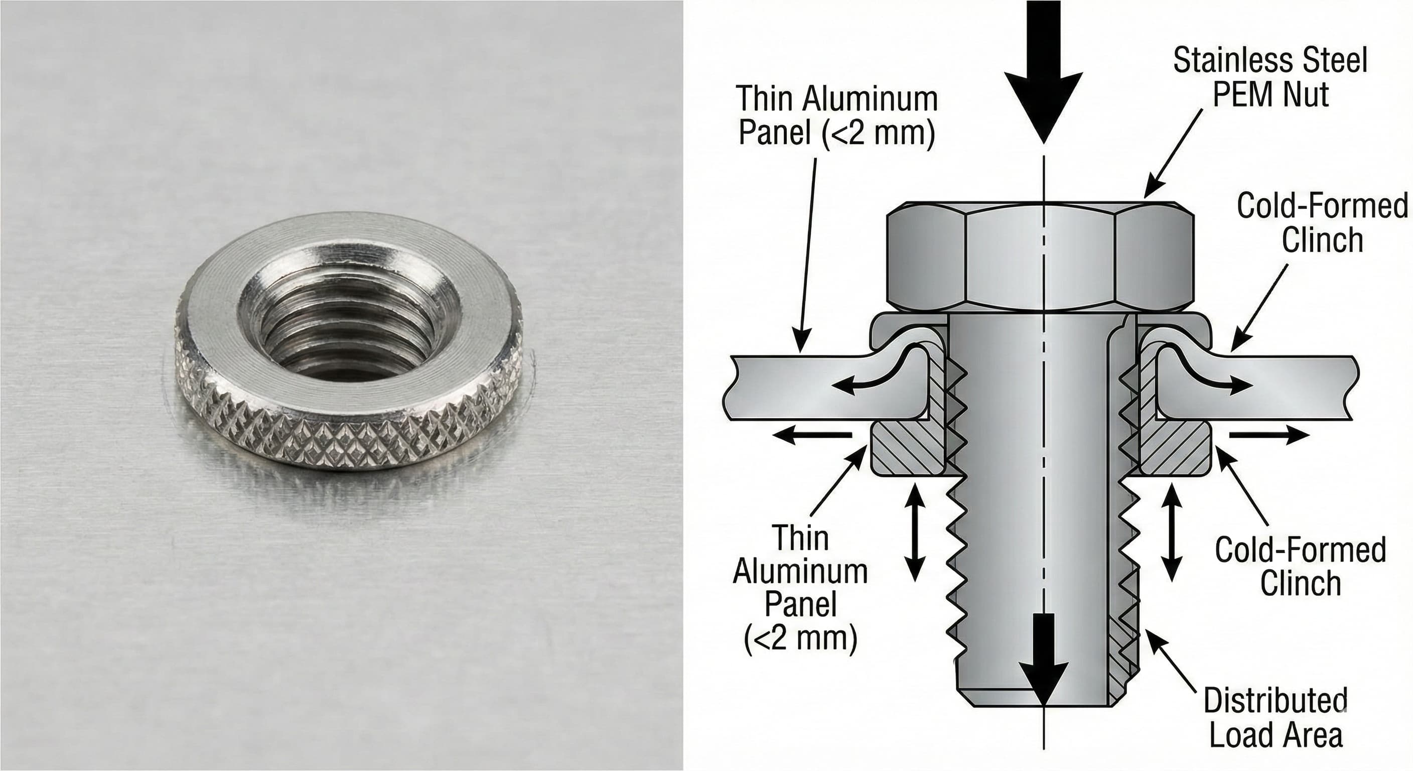
Understanding PEM Press-Fit Technology
PEM fasteners utilize a self-clinching mechanism that creates a permanent mechanical connection through controlled deformation of both the fastener and host material. Unlike traditional threaded connections that rely solely on thread engagement, press-fit nuts feature a knurled or hexagonal shank that penetrates and displaces the aluminum substrate during installation.
The fundamental principle involves three distinct zones of material interaction. The pilot diameter creates initial alignment and prevents lateral movement during installation. The clinch diameter, typically 0.2-0.4 mm larger than the pilot, generates the primary retention force through radial compression. Finally, the head flange distributes clamping loads across a surface area 3-4 times larger than the fastener diameter.
Installation requires a controlled force application, typically ranging from 8-15 kN depending on fastener size and material thickness. This force must be applied perpendicular to the panel surface with minimal lateral deviation to prevent asymmetric clinching that can reduce retention strength by up to 40%. The process creates a cold-formed joint that actually increases in strength over time due to work hardening of the displaced aluminum.
Quality sheet metal fabrication services recognize that press-fit installation requires specialized tooling and precise force control to achieve consistent results across production runs.
Material Selection Criteria
Choosing the appropriate PEM fastener material involves balancing mechanical properties, corrosion resistance, and cost considerations specific to thin aluminum applications. The three primary material options each offer distinct advantages depending on application requirements.
Stainless steel PEM nuts, typically manufactured from 303 or 416 grades, provide the highest tensile and shear strengths while maintaining excellent corrosion resistance. The 303 stainless option offers superior machinability and thread quality, with yield strengths reaching 310 MPa. However, the slight magnetic properties and higher thermal expansion coefficient compared to aluminum can create challenges in precision assemblies.
Carbon steel fasteners with zinc or zinc-nickel plating deliver maximum strength at the lowest cost point. These fasteners can achieve tensile strengths exceeding 450 MPa, making them ideal for high-load applications. The primary limitation involves galvanic compatibility, as the significant electrochemical potential difference between steel and aluminum accelerates corrosion in humid environments.
MaterialTensile Strength (MPa)Corrosion ResistanceCost FactorBest Applications303 Stainless Steel310-350Excellent2.1xMarine, food processingAluminum 6061276Good (with aluminum)1.8xAerospace, electronicsCarbon Steel (Zn plated)450-520Fair1.0xIndoor structural416 Stainless Steel380-420Very Good2.4xMedical devices Aluminum PEM nuts, manufactured from 6061-T6 or similar alloys, offer the optimal galvanic compatibility for aluminum substrates. While mechanical strength remains lower than steel alternatives, the elimination of dissimilar metal corrosion often outweighs this limitation in long-term applications. The thermal expansion match also prevents stress buildup during temperature cycling.
Critical Installation Parameters
Successful PEM fastener installation in thin aluminum requires precise control of multiple interdependent variables. Hole preparation represents the most critical factor, as dimensional accuracy directly affects retention strength and panel integrity.
Hole diameter tolerances must fall within ±0.05 mm of the specified pilot dimension to achieve optimal clinching performance. Oversized holes reduce radial compression and can decrease pullout strength by 25-35%. Undersized holes create excessive installation forces that may crack brittle aluminum alloys or cause incomplete clinching in work-hardened materials.
Edge distance requirements become particularly important in thin sections where material displacement during clinching can approach the panel edge. Minimum edge distances should equal 2.5 times the fastener diameter, with 3.0 times preferred for critical applications. This ensures adequate material volume for proper clinch formation without edge tearout.
Panel thickness compatibility ranges vary by fastener design, but most standard PEM nuts accommodate 0.5-3.0 mm aluminum sheets. Thickness uniformity across the clinch zone affects retention consistency, making material selection and our manufacturing services crucial for maintaining quality standards.
Installation force requirements scale approximately with the square of the fastener diameter and linearly with material thickness. A #8-32 fastener in 1.6 mm 6061-T6 aluminum typically requires 12-14 kN installation force, while the same fastener in 0.8 mm material needs only 7-9 kN. Excessive force can cause panel dimpling or breakthrough, while insufficient force results in incomplete clinching.
Panel Thickness (mm)Hole Tolerance (mm)Min Edge DistanceInstallation Force (kN)Typical Applications0.5-0.8+0.00/-0.053.5x diameter6-9Electronics housings0.9-1.5+0.05/-0.003.0x diameter10-13Appliance panels1.6-2.4+0.05/-0.002.8x diameter12-16Automotive components2.5-3.0+0.08/-0.002.5x diameter15-20Structural assemblies Load Distribution and Joint Design
Understanding load transfer mechanisms in PEM fastener joints enables engineers to optimize joint design for specific application requirements. Unlike conventional threaded connections where loads concentrate at the first few thread engagements, press-fit nuts distribute forces through multiple contact zones.
The primary load path begins at the fastener head flange, which creates a bearing stress distribution across the aluminum surface. Peak stresses occur at the flange edges, making head diameter selection critical for preventing aluminum yield under high clamp loads. Finite element analysis shows that increasing head diameter from 2.0 to 2.5 times the thread diameter reduces peak bearing stress by approximately 30%.
Shear loads transfer through the clinched material zone, where the deformed aluminum creates a mechanical interlock with the fastener shank. This connection can typically sustain 60-80% of the fastener's ultimate shear strength before material failure occurs in the aluminum substrate rather than the fastener itself.
Pullout resistance develops through three mechanisms: mechanical interference at the clinch diameter, friction along the shank surface, and bearing against the deformed material collar. The relative contribution of each mechanism depends on aluminum alloy properties, with softer alloys relying more heavily on mechanical interference.
For high-precision results, Get a quote in 24 hours from Microns Hub.
Joint stiffness considerations become important in dynamic loading applications where fatigue resistance depends on load distribution uniformity. PEM joints typically exhibit 15-25% lower stiffness than equivalent tapped connections due to the compliance introduced by the deformed material zone. This reduced stiffness can actually improve fatigue performance by reducing stress concentrations, but may affect resonant frequencies in vibration-sensitive applications.
Aluminum Alloy Compatibility
Different aluminum alloys respond variably to press-fit installation due to differences in work hardening characteristics, ductility, and grain structure. Understanding these material-specific behaviors enables proper fastener selection and installation parameter optimization.
6061-T6 aluminum represents the most commonly specified substrate for PEM applications, offering an excellent balance of strength, ductility, and machinability. The T6 temper provides sufficient yield strength (276 MPa) to resist excessive deformation during clinching while maintaining enough ductility to prevent cracking. Grain size uniformity in 6061 alloys ensures consistent clinching behavior across production lots.
5052-H32 aluminum offers superior corrosion resistance and excellent forming characteristics, making it suitable for complex geometries requiring IP65 sealing strategies. However, the work-hardening behavior during clinching can increase installation forces by 20-30% compared to 6061 alloys. This material also exhibits greater spring-back, potentially affecting fastener retention if installation parameters are not properly adjusted.
7075-T6 aluminum provides the highest strength option but presents challenges for PEM installation. The limited ductility and high work-hardening rate can cause incomplete clinching or material cracking around the fastener. When 7075 substrates are required, fastener selection should favor designs with reduced clinch diameters and graduated shank profiles to minimize material displacement.
AlloyTemperYield Strength (MPa)Elongation (%)PEM CompatibilityInstallation Notes6061T627612-17ExcellentStandard parameters5052H3219312-18Very GoodIncrease force 20-25%7075T65035-11FairReduce clinch diameter3003H141458-16GoodRisk of overdeformation2024T334515-20PoorCopper content issues The grain orientation relative to clinching direction can influence joint quality, particularly in rolled sheet materials where directional properties may vary by 10-15%. Optimal installation occurs when the fastener axis aligns perpendicular to the rolling direction, minimizing the risk of delamination or preferential tearing.
Quality Control and Testing Methods
Establishing robust quality control procedures for PEM installations ensures consistent joint performance and prevents field failures. Multiple inspection and testing methods provide different levels of insight into installation quality and long-term reliability.
Visual inspection remains the first line of quality control, focusing on head seating, panel deformation, and edge integrity. Properly installed fasteners should sit flush with the panel surface without creating dimples or raised areas exceeding 0.1 mm. The aluminum around the fastener should show uniform deformation patterns without cracks, tears, or excessive material buildup.
Go/no-go gauging provides a quick production-floor method for verifying clinch quality. These gauges check both the fastener protrusion on the back side and the head seating on the installation side. Typical acceptance criteria require back-side protrusion between 0.2-0.8 mm depending on panel thickness and fastener design.
Torque testing evaluates the rotational resistance of installed fasteners, which correlates with clinch quality. Under-clinched fasteners exhibit reduced torque-out values, while properly installed units typically require 80-120% of the specified minimum torque to cause rotation. This test method works particularly well for production sampling but destroys the tested joints.
Push-out testing provides quantitative data on retention strength by applying axial loads until fastener failure occurs. Test fixtures must ensure uniform load application perpendicular to the panel surface to generate meaningful data. Acceptance criteria typically require push-out forces exceeding 75% of published values, accounting for installation and material variations.
Cross-sectional analysis through metallographic preparation reveals the internal clinch geometry and material flow patterns. This destructive method provides the most comprehensive assessment of joint quality but requires specialized equipment and expertise. Key evaluation criteria include clinch diameter uniformity, material continuity, and absence of voids or cracks in the deformed zone.
Cost Optimization Strategies
Achieving cost-effective PEM fastener implementation requires balancing initial fastener costs against total assembly expenses, including labor, tooling, and quality control. Several strategies can significantly impact overall project economics without compromising performance.
Volume purchasing agreements with fastener suppliers can reduce unit costs by 15-30% while ensuring supply chain stability. Standardizing on a limited range of fastener sizes and materials simplifies inventory management and installation tooling requirements. Most applications can be adequately served with three thread sizes (#8-32, #10-32, and 1/4-20) in two head styles.
Installation automation becomes economically attractive for production volumes exceeding 10,000 units annually. Pneumatic press systems can install PEM fasteners at rates of 300-500 per hour with superior consistency compared to manual installation. The improved quality control reduces scrap rates and eliminates the need for individual fastener inspection in many applications.
When ordering from Microns Hub, you benefit from direct manufacturer relationships that ensure superior quality control and competitive pricing compared to marketplace platforms. Our technical expertise and personalized service approach means every project receives the attention to detail it deserves, often reducing total project costs through optimized design recommendations.
Design optimization can eliminate fasteners entirely in some applications through integral attachment features or snap-fit connections. However, this approach requires careful analysis of load requirements and manufacturing capabilities. PEM fasteners often provide the most cost-effective solution when removability or high strength connections are required.
Production VolumeInstallation MethodLabor Cost (€/fastener)Quality ControlTotal Cost Factor<1,000Manual press0.08-0.12100% visual1.0x1,000-10,000Pneumatic press0.04-0.0610% sampling0.7x10,000-50,000Semi-automatic0.02-0.03Statistical process0.5x>50,000Fully automatic0.01-0.015Continuous monitoring0.4x Advanced Applications and Special Considerations
Specialized applications often require modifications to standard PEM fastener designs or installation procedures to meet unique performance requirements. Understanding these advanced techniques enables engineers to expand the applicability of press-fit technology.
Sealed applications requiring environmental protection benefit from PEM fasteners with integrated O-ring grooves or sealing washers. These designs maintain the advantages of press-fit installation while providing IPX7 or higher protection levels. The sealing effectiveness depends on proper groove geometry and material compatibility between the seal and aluminum substrate.
High-temperature applications above 150°C require careful consideration of thermal expansion differences between fastener and substrate materials. Stainless steel PEM nuts in aluminum panels experience differential expansion that can either increase or decrease retention forces depending on temperature cycling patterns. Finite element thermal analysis becomes necessary for critical applications.
Electromagnetic compatibility (EMC) requirements in electronic enclosures may favor aluminum PEM fasteners to maintain conductivity across joints. The clinching process creates a gas-tight metal-to-metal contact that provides excellent electrical continuity with resistance values typically below 0.001 ohms. This performance surpasses most gasketed or painted joint interfaces.
Multi-layer assemblies present unique challenges when installing PEM fasteners through stacked materials. The fastener must clinch effectively in the primary layer while avoiding damage to secondary layers. Stack-up tolerances become critical, as variations can prevent complete clinching or cause breakthrough into adjacent components.
Vibration environments require enhanced retention methods beyond standard press-fit mechanisms. Thread locking compounds, staking operations, or specialized fastener designs with mechanical locking features may be necessary to prevent loosening under dynamic loads. Testing per MIL-STD-810 or similar standards validates performance in specific vibration spectra.
Troubleshooting Common Installation Problems
Identifying and resolving PEM installation issues requires systematic analysis of failure modes and their root causes. Most problems stem from improper hole preparation, incorrect installation parameters, or material compatibility issues.
Incomplete clinching manifests as reduced retention strength and visible gaps between the fastener head and panel surface. This condition typically results from insufficient installation force, oversized holes, or work-hardened material that resists deformation. Solutions include increasing installation force by 10-15%, verifying hole dimensions, and annealing work-hardened materials when possible.
Panel distortion around installed fasteners indicates excessive installation force or inadequate material support during clinching. The thin aluminum yields under concentrated loads, creating dimples or raised areas that affect assembly fit-up. Reducing installation force and improving backing plate support typically resolves this issue without compromising retention strength.
Fastener rotation during assembly suggests inadequate clinch formation or contaminated interfaces that reduce friction. Oil, cutting fluids, or oxidation can prevent proper material engagement during installation. Cleaning procedures using isopropanol or alkaline degreasers restore proper clinching behavior in most cases.
Edge tearout occurs when insufficient material exists to contain the clinching forces, typically due to inadequate edge distances or material defects near the installation site. Prevention requires strict adherence to minimum edge distance specifications and material inspection to identify inclusions or laminations that could propagate into tears.
Cracking around installed fasteners indicates material brittleness or excessive stress concentrations during installation. This problem occurs most frequently with high-strength aluminum alloys or materials subjected to prior cold working. Solutions include stress relief annealing, fastener design modifications to reduce clinch diameter, or switching to more ductile substrate materials.
Frequently Asked Questions
What is the minimum aluminum thickness suitable for PEM press-fit nuts?
Most standard PEM nuts require a minimum thickness of 0.5 mm for proper clinching in aluminum substrates. Below this thickness, the material lacks sufficient volume to form a reliable mechanical interlock. Specialized thin-sheet fasteners can accommodate materials as thin as 0.3 mm, but these require modified installation procedures and may have reduced load capacity.
How do I prevent galvanic corrosion when using steel PEM fasteners in aluminum?
Galvanic corrosion prevention requires eliminating moisture and electrolyte contact between dissimilar metals. Use stainless steel or aluminum PEM fasteners when possible, apply dielectric coatings or sealants at the interface, or ensure the assembly operates in dry environments. Zinc-nickel plated steel fasteners offer improved compatibility compared to standard zinc plating.
Can PEM fasteners be removed and reinstalled in aluminum panels?
PEM fasteners create permanent installations that cannot be safely removed without damaging the aluminum substrate. The clinching process deforms both materials, making reversal impossible. Applications requiring removability should use conventional nuts with backing plates or cage nuts designed for thin sheet applications.
What installation force is required for different PEM fastener sizes in aluminum?
Installation forces vary by fastener size and aluminum thickness. Typical ranges include 6-9 kN for #6-32 fasteners, 10-13 kN for #8-32, 12-16 kN for #10-32, and 18-25 kN for 1/4-20 sizes in 1.6 mm aluminum. Consult manufacturer specifications for exact values, as forces can vary by 20-30% between different fastener designs.
How do I verify proper PEM fastener installation quality?
Quality verification combines visual inspection, dimensional checking, and functional testing. Look for flush head seating, uniform material deformation, and 0.2-0.8 mm back-side protrusion. Torque testing should require 80-120% of specified values to cause fastener rotation. Push-out testing provides quantitative retention strength data for critical applications.
What happens if the hole size is incorrect for PEM installation?
Oversized holes reduce retention strength by 25-35% and may prevent complete clinching. Undersized holes increase installation forces and can crack brittle materials or cause incomplete fastener seating. Hole tolerances must remain within ±0.05 mm of specified dimensions for optimal performance.
Are there temperature limitations for PEM fasteners in aluminum assemblies?
Standard PEM installations function reliably from -40°C to +150°C. Higher temperatures require analysis of differential thermal expansion between fastener and substrate materials. Stainless steel fasteners expand less than aluminum, potentially reducing retention forces during heating cycles. Aluminum PEM fasteners provide better thermal compatibility for extreme temperature applications.
MICRONS HUB DV Ε.Ε. · VAT: EL803129638 · GEMI: 190254227000 · Industrial Area, Street B, Number 4, 71601 Heraklion, Crete, Greece