From STEP to G-Code: How We Verify Your CAD for Manufacturability
Converting CAD files to manufacturable parts requires rigorous verification at every stage of the STEP-to-G-code pipeline. At Microns Hub, we've developed systematic protocols that catch design issues before they become costly production failures, ensuring your components meet both dimensional specifications and manufacturing constraints.
Our verification process integrates geometric analysis, material property validation, and toolpath optimization to deliver parts that match your engineering intent while maintaining cost-effectiveness and delivery schedules.
- STEP file validation identifies geometric anomalies and non-manifold surfaces that could compromise machining accuracy
- DFM analysis evaluates feature accessibility, tool clearances, and optimal machining sequences before programming begins
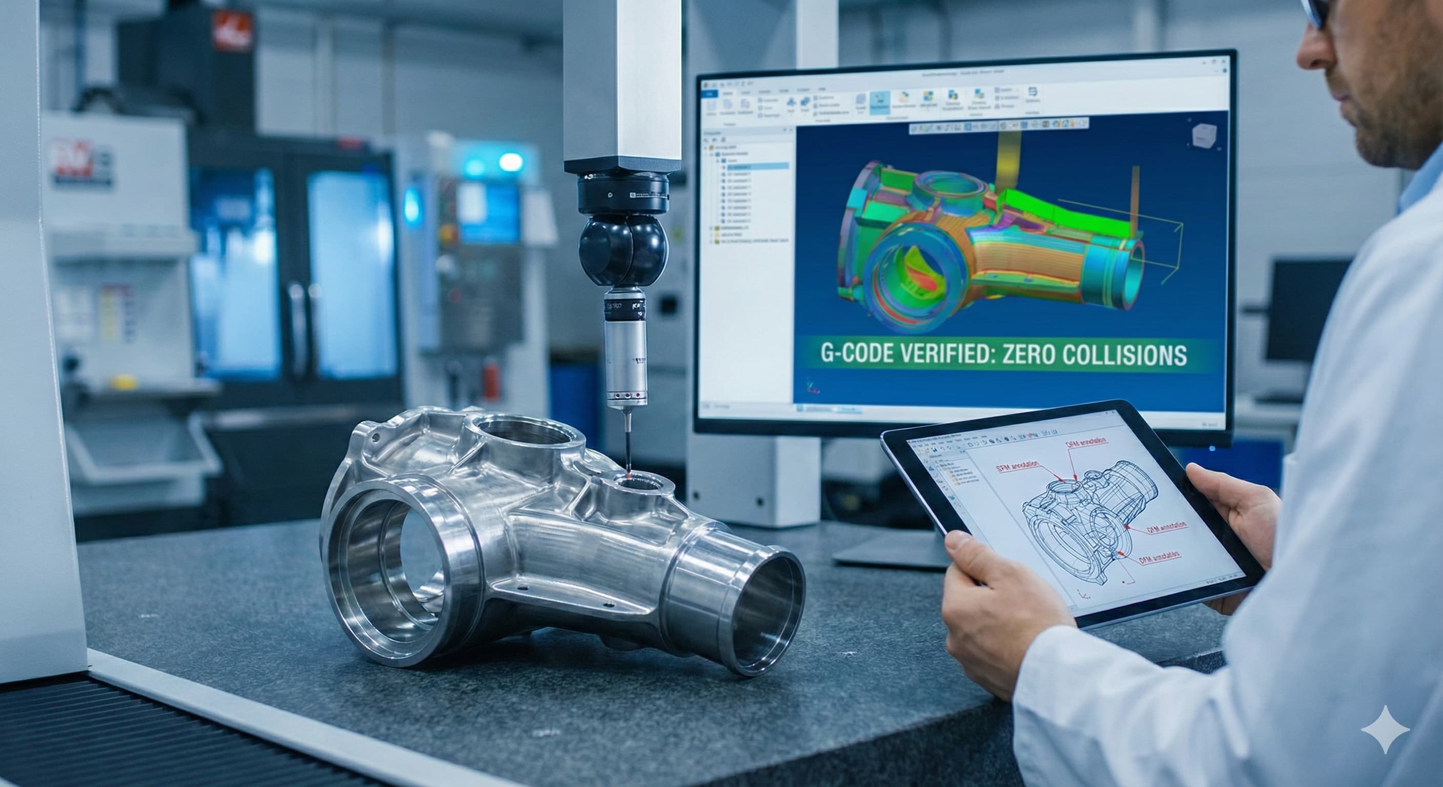
- G-code verification simulates actual cutting conditions to prevent collisions, optimize cycle times, and ensure dimensional compliance
- Material-specific adjustments account for thermal expansion, work hardening, and cutting force variations during production
STEP File Analysis and Geometric Validation
The foundation of reliable manufacturing begins with comprehensive STEP file analysis. Our engineering team performs multi-layered validation using specialized CAD analysis software that examines geometric integrity, surface continuity, and dimensional consistency against manufacturing tolerances.
STEP (Standard for the Exchange of Product Data) files often contain subtle geometric issues invisible in standard CAD viewers. Non-manifold edges, self-intersecting surfaces, and microscopic gaps between adjacent faces can cause catastrophic failures during G-code generation. We employ automated geometric healing algorithms followed by manual verification to ensure every surface is manufacturable.
Surface normal validation is particularly critical for complex geometries. Inverted normals can cause tool path calculation errors, leading to gouging or incomplete material removal. Our validation process checks normal consistency across all surfaces, identifying and correcting orientation issues before machining begins.
Validation CheckTolerance RangeImpact if FailedCorrection MethodSurface Continuity±0.001 mmTool path deviationsSurface healing algorithmsNormal OrientationVector consistencyGouging or missed materialManual normal correctionEdge ConnectivityZero gap toleranceG-code generation failureEdge reconstructionDimensional Accuracy±0.01 mmPart rejectionGeometry scaling/correction
Unit consistency verification prevents scaling errors that plague international collaborations. A part designed in inches but imported as millimeters results in components 25.4 times smaller than intended. Our validation protocols automatically detect unit discrepancies and flag them for engineering review before processing continues.
Design for Manufacturability Assessment
DFM evaluation transforms theoretical designs into practical manufacturing solutions. Our assessment focuses on feature accessibility, tool clearance requirements, and optimal machining sequences that minimize setup changes while maintaining dimensional accuracy.
Sharp internal corners present immediate manufacturability challenges. End mills create radiused corners with minimum radii equal to half the tool diameter. Features requiring 0.5 mm internal radii demand specialized micro-tooling that significantly increases cycle times and costs. We recommend design modifications that accommodate standard tooling while preserving functional requirements.
Aspect ratio analysis evaluates the relationship between feature depth and width. Deep, narrow slots with aspect ratios exceeding 5:1 require specialized long-reach tooling and create challenges with chip evacuation and vibration control. For deep pocket features, we recommend design modifications that improve tool access and reduce machining forces.
Wall thickness evaluation ensures structural integrity throughout machining operations. Thin-walled features can deflect under clamping forces or cutting loads, causing dimensional deviations and potential part damage. Minimum wall thickness recommendations vary by material, but typically range from 1.0 mm for aluminum alloys to 2.0 mm for steel components.
Material-Specific Design Considerations
Different materials impose unique manufacturing constraints that influence design recommendations. Aluminum 6061-T6 offers excellent machinability with minimal work hardening, allowing aggressive cutting parameters and tight tolerance achievement. However, its relatively low elastic modulus (69 GPa) requires careful consideration of deflection under machining forces.
Stainless steel 316L presents challenges with work hardening during cutting operations. Features that require multiple passes or interrupted cuts can develop hardened surface layers that accelerate tool wear and compromise surface finish. Our DFM analysis identifies these potential issues and recommends design modifications or specialized tooling strategies.
MaterialMin Wall ThicknessMax Aspect RatioInternal Radius LimitTolerance CapabilityAl 6061-T61.0 mm8:10.2 mm±0.025 mmSS 316L1.5 mm6:10.3 mm±0.05 mmTi 6Al-4V2.0 mm4:10.5 mm±0.075 mmInconel 7182.5 mm3:10.8 mm±0.1 mm
CAM Programming and Toolpath Optimization
Computer-Aided Manufacturing (CAM) programming translates verified geometry into optimized toolpaths that balance cycle time, tool life, and dimensional accuracy. Our programming approach considers material properties, workholding constraints, and machine capabilities to generate efficient cutting strategies.
Roughing operations remove bulk material using aggressive cutting parameters while leaving consistent stock allowances for finishing passes. We typically maintain 0.2-0.5 mm stock allowance depending on feature geometry and tolerance requirements. Adaptive clearing strategies vary feed rates and stepover distances based on material engagement, reducing cutting forces and extending tool life.
Semi-finishing operations create uniform surface conditions for final passes while addressing geometric transitions between features. These operations are particularly critical for complex 3D surfaces where surface normal changes require careful attention to tool orientation and cutting direction.
Finishing passes achieve final dimensions and surface requirements using optimized cutting parameters. Tool selection balances surface finish requirements with productivity goals. Carbide end mills with specialized coatings can achieve surface finishes of Ra 0.8 μm or better in aluminum alloys, while maintaining reasonable cycle times.
Advanced Toolpath Strategies
High-speed machining (HSM) techniques enable efficient processing of complex geometries while maintaining dimensional accuracy. HSM strategies use light axial depths of cut (typically 0.1-0.3 mm) combined with high feed rates to maintain optimal chip loads while minimizing cutting forces.
Trochoidal milling patterns create smooth, continuous toolpaths that eliminate sharp direction changes and reduce machine acceleration/deceleration cycles. These patterns are particularly effective for slotting operations and deep pocket machining where conventional toolpaths would create excessive cutting forces.
For high-precision results, Request a free quote and get pricing in 24 hours from Microns Hub.
Climb milling orientation provides superior surface finish and dimensional accuracy compared to conventional milling. The cutting action pushes the workpiece against the fixture rather than lifting it, reducing vibration and improving surface quality. However, machine backlash compensation must be properly calibrated to prevent tool engagement issues.
G-Code Verification and Simulation
G-code verification represents the final quality gate before physical machining begins. Our simulation software creates virtual representations of cutting operations that identify potential collisions, verify dimensional accuracy, and optimize cycle times.
Collision detection algorithms check tool clearances throughout the entire machining cycle, including rapid positioning moves and tool changes. The simulation considers actual machine geometry, including spindle dimensions, tool holder configurations, and workholding fixtures. This comprehensive approach prevents costly crashes that could damage equipment or compromise part quality.
Dimensional verification compares simulated part geometry against original CAD specifications. The simulation accounts for tool deflection, thermal effects, and cutting force variations to predict final part dimensions within ±0.005 mm accuracy. This predictive capability allows process adjustments before machining begins.
Cycle time optimization balances productivity goals with quality requirements. The simulation identifies opportunities to increase feed rates during less critical operations while maintaining conservative parameters for tolerance-critical features. Typical optimization results in 15-25% cycle time reductions without compromising quality.
Simulation ParameterVerification ToleranceTypical AccuracyAdjustment RangeDimensional Accuracy±0.01 mm±0.005 mm±0.002 mm compensationSurface FinishRa 1.6 μmRa 0.8 μm±0.4 μm variationCycle Time±5% variance±2% variance10-30% optimization potentialTool Life±10% prediction±5% prediction20-50% improvement possible
Material Removal Simulation
Advanced material removal simulation tracks cutting conditions throughout the machining cycle, identifying areas of excessive tool loading or insufficient material engagement. This analysis is particularly valuable for complex 3D surfaces where cutting conditions vary continuously.
Cutting force prediction algorithms consider material properties, tool geometry, and cutting parameters to estimate machining forces throughout each operation. High force areas receive special attention to ensure adequate workholding and prevent part distortion during machining.
Thermal analysis predicts heat generation and distribution during cutting operations. Excessive temperatures can cause thermal expansion that compromises dimensional accuracy or work hardening that accelerates tool wear. The simulation identifies high-temperature areas and recommends coolant strategies or parameter adjustments.
Quality Control Integration
Quality control integration ensures manufactured parts meet specifications through systematic measurement and process validation. Our quality protocols combine in-process monitoring with post-machining inspection to maintain consistent results across production quantities.
Statistical Process Control (SPC) methods track key dimensional characteristics throughout production runs. Control charts identify process drift before parts fall outside specification limits, enabling proactive adjustments that prevent defective parts. We typically achieve Cpk values of 1.33 or higher for critical dimensions.
Coordinate Measuring Machine (CMM) inspection provides comprehensive dimensional validation for complex geometries. Our programming generates automated inspection routines that measure critical features while minimizing setup time. Typical inspection accuracy is ±0.002 mm with repeatability of ±0.001 mm.
When ordering from Microns Hub, you benefit from direct manufacturer relationships that ensure superior quality control and competitive pricing compared to marketplace platforms. Our integrated approach to design verification, manufacturing optimization, and quality assurance delivers consistent results that meet your engineering requirements while maintaining competitive delivery schedules.
Traceability and Documentation
Complete documentation packages accompany each manufactured component, providing full traceability from raw material certification through final inspection results. Material certifications verify chemistry and mechanical properties according to applicable standards such as ASTM B209 for aluminum plate or ASTM A240 for stainless steel sheet.
First Article Inspection (FAI) reports document dimensional compliance for initial production parts. These reports include actual measured values for all specified dimensions, surface finish measurements, and material property verification. FAI approval establishes the manufacturing baseline for subsequent production quantities.
Process control documentation records cutting parameters, tool usage, and cycle times for each manufactured part. This information enables rapid process recreation for repeat orders and provides valuable data for continuous improvement initiatives.
Integration with Manufacturing Services
Our verification protocols integrate seamlessly with our manufacturing services to provide comprehensive solutions for complex components. Multi-operation parts requiring both CNC machining and sheet metal fabrication services benefit from coordinated planning that optimizes the complete manufacturing sequence.
Assembly considerations influence individual part design recommendations. Components requiring press fits, threaded fasteners, or welded joints receive specialized analysis to ensure proper fit and function. Tolerance stack-up analysis prevents interference issues that could compromise assembly operations.
Secondary operations such as heat treatment, surface coating, or finishing processes are considered during initial design verification. These operations can affect part dimensions through thermal expansion, coating thickness buildup, or material removal during finishing. Our verification process accounts for these effects to ensure final parts meet specifications.
Cost Optimization Strategies
Cost optimization begins during the verification phase through design modifications that reduce manufacturing complexity without compromising functionality. Simple changes such as increasing corner radii, adjusting hole positions for standard drill sizes, or modifying surface finish requirements can significantly reduce production costs.
Material utilization analysis identifies opportunities to minimize waste through optimal part orientation and nesting strategies. For precision gear components and similar high-value parts, material savings of 15-30% are often achievable through careful planning.
Tooling standardization reduces setup complexity and inventory requirements. Our verification process identifies opportunities to use standard tooling across multiple features, reducing cycle times and simplifying programming requirements.
Optimization CategoryTypical Cost ReductionImplementation ComplexityQuality ImpactDesign Simplification15-25%LowNeutral or positiveMaterial Optimization10-20%MediumNeutralTooling Standardization8-15%MediumNeutralProcess Integration12-30%HighPositive
Frequently Asked Questions
How do you handle STEP files with missing or corrupted geometry?
We use automated healing algorithms combined with manual reconstruction techniques to repair geometric defects. Our process includes surface reconstruction for missing faces, edge connectivity restoration, and normal vector correction. If healing isn't possible, we provide detailed feedback with recommended design modifications to resolve the issues.
What tolerance capabilities can you achieve with different materials?
Tolerance capabilities depend on material properties, part geometry, and manufacturing processes. For aluminum 6061-T6, we routinely achieve ±0.025 mm on machined features. Stainless steel 316L typically achieves ±0.05 mm, while more challenging materials like Inconel 718 are held to ±0.1 mm. Tighter tolerances are possible with specialized tooling and additional operations.
How do you verify toolpath accuracy before machining?
Our G-code verification process uses advanced simulation software that models the complete machining process, including tool deflection, cutting forces, and thermal effects. The simulation compares predicted part geometry against CAD specifications with ±0.005 mm accuracy, allowing process optimization before physical machining begins.
What design modifications do you recommend for cost reduction?
Common cost-reduction modifications include increasing internal corner radii to accommodate larger tools, adjusting hole sizes to standard drill diameters, reducing surface finish requirements where possible, and modifying part orientation to minimize material waste. We provide detailed recommendations that maintain functionality while reducing manufacturing complexity.
How do you handle parts requiring multiple manufacturing processes?
Multi-process components receive coordinated planning that optimizes the complete manufacturing sequence. We consider tolerance stack-up effects, material property changes from heat treatment, and dimensional variations from secondary operations. Our integrated approach ensures all processes work together to meet final part specifications.
What quality documentation do you provide with manufactured parts?
Complete documentation packages include material certifications, dimensional inspection reports, surface finish measurements, and First Article Inspection (FAI) documentation when required. We also provide process control records showing cutting parameters, tool usage, and cycle times for full traceability.
How do you optimize cycle times while maintaining quality?
Cycle time optimization uses advanced toolpath strategies such as adaptive clearing, trochoidal milling, and high-speed machining techniques. Our simulation software identifies opportunities to increase feed rates during non-critical operations while maintaining conservative parameters for tolerance-critical features, typically achieving 15-25% time reductions without compromising quality.
MICRONS HUB DV Ε.Ε. · VAT: EL803129638 · GEMI: 190254227000 · Industrial Area, Street B, Number 4, 71601 Heraklion, Crete, Greece