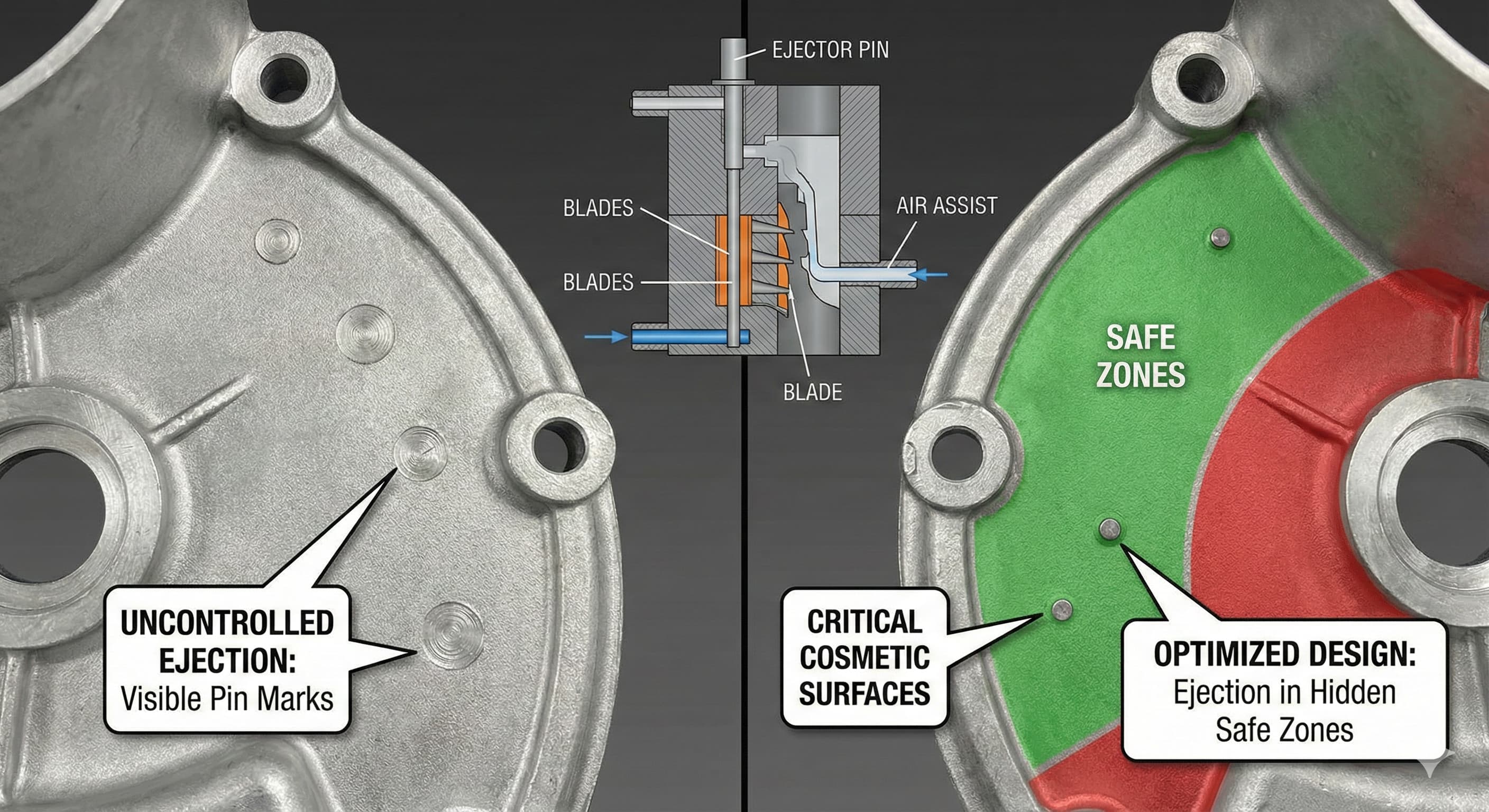
Ejector Pin Marks: Designing "Safe Zones" on Cosmetic Cast Surfaces
Ejector pin marks represent one of the most persistent quality challenges in cast part manufacturing, particularly when components feature visible cosmetic surfaces. These seemingly minor surface imperfections can transform an otherwise perfect casting into a rejection, driving up costs and extending delivery timelines. The strategic placement of ejector pins requires a systematic approach that balances manufacturing efficiency with aesthetic requirements.
Understanding ejector pin mark formation begins with recognizing the fundamental physics involved. During ejection, localized stress concentrations create permanent deformation zones ranging from 0.2 mm to 2.0 mm in diameter, depending on pin geometry and material properties. These marks appear as circular depressions, raised areas, or textural variations that become particularly pronounced on polished or anodized surfaces.
Key Takeaways
- Ejector pin marks form permanent surface defects 0.2-2.0 mm in diameter through localized stress concentration during part ejection
- Strategic "safe zone" placement requires analyzing part geometry, draft angles, and cosmetic surface requirements early in design phase
- Pin diameter, ejection force, and material hardness directly influence mark severity and visibility on finished surfaces
- Advanced techniques including blade ejection, stripper plates, and air assist systems can minimize or eliminate visible marking
Understanding Ejector Pin Mark Formation
The formation of ejector pin marks occurs through a complex interaction of mechanical forces, material properties, and thermal conditions. When ejector pins contact the cast part, they create localized stress fields that exceed the material's elastic limit, resulting in permanent plastic deformation.
Material hardness plays a critical role in mark severity. Aluminum alloys like A380 (typical hardness 80-100 HB) show different marking characteristics compared to A356-T6 (hardness 70-95 HB). Softer materials generally exhibit more pronounced marking, while harder alloys may show less visible deformation but can experience surface cracking under excessive ejection forces.
Temperature effects compound the marking problem. Parts ejected at temperatures above 200°C demonstrate increased marking susceptibility due to reduced yield strength. Conversely, parts allowed to cool below 150°C before ejection show significantly reduced mark depth, though this cooling period impacts cycle time and productivity.
| Material Grade | Hardness (HB) | Typical Mark Depth (mm) | Recommended Pin Diameter (mm) |
|---|---|---|---|
| A380 (As-Cast) | 80-100 | 0.15-0.30 | 6-10 |
| A356-T6 | 70-95 | 0.10-0.25 | 8-12 |
| A413 | 85-105 | 0.12-0.28 | 6-10 |
| Zinc Alloy #3 | 95-115 | 0.08-0.20 | 5-8 |
Pin geometry significantly influences mark formation patterns. Standard cylindrical pins with 0.5-1.0 mm radius edges create circular impressions, while pins with larger radius edges (2-3 mm) distribute forces over greater surface areas, reducing mark severity. However, larger radius pins require increased ejection forces and may cause part distortion in thin-walled sections.
Safe Zone Design Principles
Effective safe zone design begins with comprehensive surface analysis during the initial design phase. Cosmetic surfaces require classification into three categories: Class A (visible and critical), Class B (visible but non-critical), and Class C (hidden or non-visible). This classification system guides ejector pin placement strategy and acceptable marking tolerances.
Draft angle optimization directly impacts safe zone availability. Surfaces with adequate draft angles (typically 1-3 degrees for aluminum casting) provide natural ejection assistance, reducing required pin forces and expanding potential safe zone locations. Insufficient draft angles force designers to place pins on cosmetic surfaces or risk part damage during ejection.
Geometric analysis reveals optimal safe zone characteristics. Flat surfaces perpendicular to ejection direction provide ideal pin placement opportunities, as forces distribute evenly without creating stress concentrations. Curved surfaces require careful analysis of local geometry, with concave areas generally preferred over convex surfaces for pin placement.
When working with sand casting applications for large components, safe zone planning becomes even more critical due to the larger surface areas and increased visibility of defects.
Ejector Pin Sizing and Force Calculations
Proper ejector pin sizing requires calculating the minimum pin diameter needed to prevent buckling while minimizing contact pressure on part surfaces. The critical buckling load for ejector pins follows Euler's formula, modified for manufacturing conditions:
P_critical = (π² × E × I) / (K × L²)
Where E represents the pin material's elastic modulus (typically 200 GPa for tool steel), I equals the area moment of inertia, K is the effective length factor (2.0 for pinned-free conditions), and L represents the unsupported pin length.
Contact pressure calculations determine marking potential. Pressure P = F/A, where F represents ejection force and A equals pin contact area. Maintaining contact pressures below 50 MPa for aluminum alloys generally prevents visible marking on cosmetic surfaces.
| Pin Diameter (mm) | Max Unsupported Length (mm) | Contact Pressure at 500N (MPa) | Recommended Application |
|---|---|---|---|
| 4 | 80 | 39.8 | Light-duty, cosmetic surfaces |
| 6 | 120 | 17.7 | Standard applications |
| 8 | 160 | 9.9 | Heavy-duty, minimal marking |
| 10 | 200 | 6.4 | Large parts, distributed loads |
Force distribution strategies include using multiple smaller pins rather than fewer large pins. This approach spreads ejection loads across wider areas while maintaining individual pin forces within acceptable limits. For example, four 6 mm pins provide equivalent contact area to one 12 mm pin while offering greater placement flexibility.
Advanced Ejection Techniques
Blade ejection systems offer superior solutions for parts with extensive cosmetic surfaces. These systems use thin, flat ejector elements (typically 1-2 mm thick) that contact parts along linear edges rather than circular points. Blade ejectors distribute forces over larger areas, reducing contact pressures by 60-80% compared to conventional pins.
Stripper plate ejection provides the ultimate solution for eliminating ejector marks on cosmetic surfaces. The stripper plate contacts the entire part perimeter simultaneously, creating uniform ejection forces without localized stress concentrations. However, this system requires precise machining and adds complexity to die design.
Air assist ejection combines mechanical pins with pressurized air injection. Air pressure (typically 0.3-0.8 MPa) supplements mechanical ejection forces, allowing smaller pins or reduced pin forces. This technique proves particularly effective for thin-walled castings where conventional ejection might cause distortion.
For high-precision results,Submit your project for a 24-hour quote from Microns Hub.
Sequential ejection timing optimizes force application throughout the ejection cycle. Initial low-force contact establishes part stability, followed by progressive force increases as the part separates from die surfaces. This approach reduces peak contact pressures while maintaining reliable ejection performance.
Surface Treatment Considerations
Post-casting surface treatments significantly influence ejector pin mark visibility and acceptability. Anodizing processes, particularly Type II sulfuric acid anodizing, tend to highlight surface irregularities including ejector pin marks. The anodic oxide layer forms differently over deformed areas, creating visible color variations even when dimensional differences remain minimal.
Powder coating applications provide excellent ejector mark concealment due to the coating's ability to fill minor surface depressions. Film thicknesses of 60-120 micrometers effectively mask pin marks up to 0.2 mm depth while providing durable surface protection.
Mechanical surface treatments like shot peening or tumbling can reduce ejector mark visibility through controlled surface texturing. These processes create uniform surface roughness that camouflages localized deformation patterns. However, dimensional changes from material removal must be considered in part design.
| Surface Treatment | Mark Visibility Reduction (%) | Typical Cost Impact (€/part) | Processing Time (hours) |
|---|---|---|---|
| As-Cast | 0 | 0 | 0 |
| Shot Peening | 70-85 | 2-5 | 0.5-1.0 |
| Powder Coating | 85-95 | 5-12 | 2-4 |
| Anodizing Type II | -20 to +10 | 8-15 | 3-6 |
| Chemical Etching | 60-80 | 3-8 | 1-2 |
Chemical etching provides another approach for mark minimization. Controlled acid etching removes 0.05-0.15 mm of surface material, effectively eliminating shallow pin marks while creating uniform surface texture. This process requires precise masking to protect critical dimensions and threaded features.
Die Design Optimization
Die design optimization begins with comprehensive ejection analysis during the initial design phase. Modern CAD systems enable finite element analysis of ejection stresses, allowing designers to predict pin mark locations and severity before die construction begins.
Ejector pin placement algorithms consider multiple factors simultaneously: part geometry, draft angles, surface classification, structural integrity, and manufacturing constraints. Optimization software ranks potential pin locations based on weighted criteria, ensuring cosmetic surfaces receive appropriate protection.
When integrating with precision CNC machining services for secondary operations, ejector pin locations must consider subsequent machining requirements and fixturing needs.
Progressive ejection systems sequence pin activation to minimize peak forces. Initial pins engage non-cosmetic surfaces, providing part stability before cosmetic surface pins activate. This approach reduces marking forces while maintaining ejection reliability.
Thermal management within die systems affects ejection requirements. Optimized cooling channels maintain uniform die temperatures, reducing part adherence and ejection forces. Temperature differentials above 30°C between die sections can double required ejection forces.
Quality Control and Inspection
Quality control protocols for ejector pin marks require standardized inspection procedures and acceptance criteria. Visual inspection standards typically classify marks by diameter, depth, and location relative to cosmetic surfaces.
Dimensional measurement of pin marks uses contact and non-contact methods. Stylus profilometry provides precise depth measurements with 0.01 mm resolution, while optical scanning systems capture complete mark geometry including diameter and edge characteristics.
Statistical process control tracks ejector pin mark trends over production runs. Control charts monitor mark depth, frequency, and location patterns, enabling early detection of die wear or process parameter drift.
| Inspection Method | Resolution (mm) | Inspection Time (seconds) | Equipment Cost (€) |
|---|---|---|---|
| Visual Inspection | 0.1 | 30-60 | 100-500 |
| Stylus Profilometry | 0.001 | 120-300 | 15,000-50,000 |
| Optical Scanning | 0.005 | 60-180 | 25,000-100,000 |
| Coordinate Measuring Machine | 0.001 | 180-600 | 80,000-300,000 |
Acceptance criteria development requires collaboration between design, manufacturing, and quality teams. Criteria must balance cosmetic requirements with manufacturing feasibility, considering factors like part cost, production volume, and end-use application.
Cost Impact Analysis
Ejector pin mark mitigation carries significant cost implications across multiple manufacturing phases. Design modifications to eliminate cosmetic surface ejection can increase die complexity by 15-30%, directly impacting tooling costs.
Alternative ejection systems like stripper plates or blade ejectors typically add €5,000-€25,000 to die costs depending on part complexity and die size. However, these investments often prove economical for high-volume production where part rejection costs exceed tooling premiums.
Secondary operations to remove or mask ejector pin marks range from €1-€15 per part depending on treatment type and part size. Manual polishing operations for mark removal can cost €8-€20 per part while adding 30-90 minutes to processing time.
When ordering from Microns Hub, you benefit from direct manufacturer relationships that ensure superior quality control and competitive pricing compared to marketplace platforms. Our technical expertise in ejector pin placement and die design optimization means every casting project receives the attention to detail necessary for cosmetic surface requirements.
Scrap and rework costs from rejected parts due to ejector pin marks typically range from €50-€500 per part depending on material costs, machining complexity, and delivery urgency. These costs often exceed ejection system optimization investments within the first few thousand parts produced.
Integration with Manufacturing Services
Successful ejector pin mark management requires integration across multiple manufacturing processes. When components require post-casting operations through our manufacturing services, ejector pin locations must coordinate with fixturing and machining requirements.
Secondary machining operations can eliminate ejector pin marks through strategic material removal. However, this approach requires careful coordination between casting and machining teams to ensure adequate stock allowances and dimensional control.
Assembly considerations influence ejector pin placement when marks occur on surfaces that interface with other components. Gasket sealing surfaces, bearing mounting areas, and threaded features require special attention to prevent functional problems from ejector pin marking.
Heat treatment processes, particularly T6 tempering for structural aluminum parts, can affect ejector pin mark visibility through microstructural changes and stress relief patterns.
Frequently Asked Questions
What causes ejector pin marks to appear darker after anodizing?
Ejector pin marks appear darker after anodizing because the localized plastic deformation creates different crystal structures in the aluminum. These deformed areas have altered surface energy and porosity, causing the anodic oxide layer to form with different thickness and density. The result is visible color variation even when the dimensional differences are minimal.
How do I calculate the minimum ejector pin diameter to prevent buckling?
Use Euler's buckling formula: P_critical = (π² × E × I) / (K × L²). For tool steel pins (E = 200 GPa), calculate the area moment of inertia I = πd⁴/64, use K = 2.0 for pinned-free conditions, and L as unsupported length. Ensure your required ejection force stays below 70% of the calculated critical load for safety margin.
Can ejector pin marks be completely eliminated from visible surfaces?
Yes, through proper design techniques including stripper plate ejection, blade ejectors, or strategic pin placement in non-visible areas. Stripper plates eliminate point contact entirely, while blade ejectors distribute forces linearly. Alternative approaches include air-assist ejection or designing parting lines to place all pins on hidden surfaces.
What's the maximum acceptable ejector pin mark depth for cosmetic surfaces?
For Class A cosmetic surfaces, marks should not exceed 0.05 mm depth with diameters under 2.0 mm. Class B surfaces can accept marks up to 0.15 mm depth. These limits apply to parts with natural aluminum finish; powder-coated parts can accept deeper marks (up to 0.20 mm) due to coating fill-in effects.
How does part temperature during ejection affect pin mark severity?
Higher ejection temperatures increase mark severity due to reduced material yield strength. Parts ejected above 200°C show 40-60% deeper marks than those cooled to 150°C. However, cooling time impacts cycle efficiency. Optimal ejection temperature balances mark severity against productivity requirements, typically 160-180°C for aluminum casting.
What ejector pin material provides the best surface finish on aluminum castings?
Hardened tool steel pins (58-62 HRC) with polished surfaces provide optimal results. H13 tool steel offers excellent wear resistance and thermal stability. Pin surfaces should be polished to Ra 0.2 μm or better and treated with TiN coating for extended life. Avoid softer pin materials that can gall or deform during service.
How do I retrofit existing dies to reduce ejector pin marking?
Retrofit options include increasing pin diameter (if space allows), adding more pins to distribute loads, converting to blade ejectors in critical areas, or implementing air-assist systems. Each approach requires careful analysis of existing die geometry and structural limitations. Complete stripper plate conversion typically requires extensive die modification and may not be cost-effective for existing tooling.
MICRONS HUB DV Ε.Ε. · VAT: EL803129638 · GEMI: 190254227000 · Industrial Area, Street B, Number 4, 71601 Heraklion, Crete, Greece