Designing Draft Angles for Metal Castings: A Practical Guide for Engineers
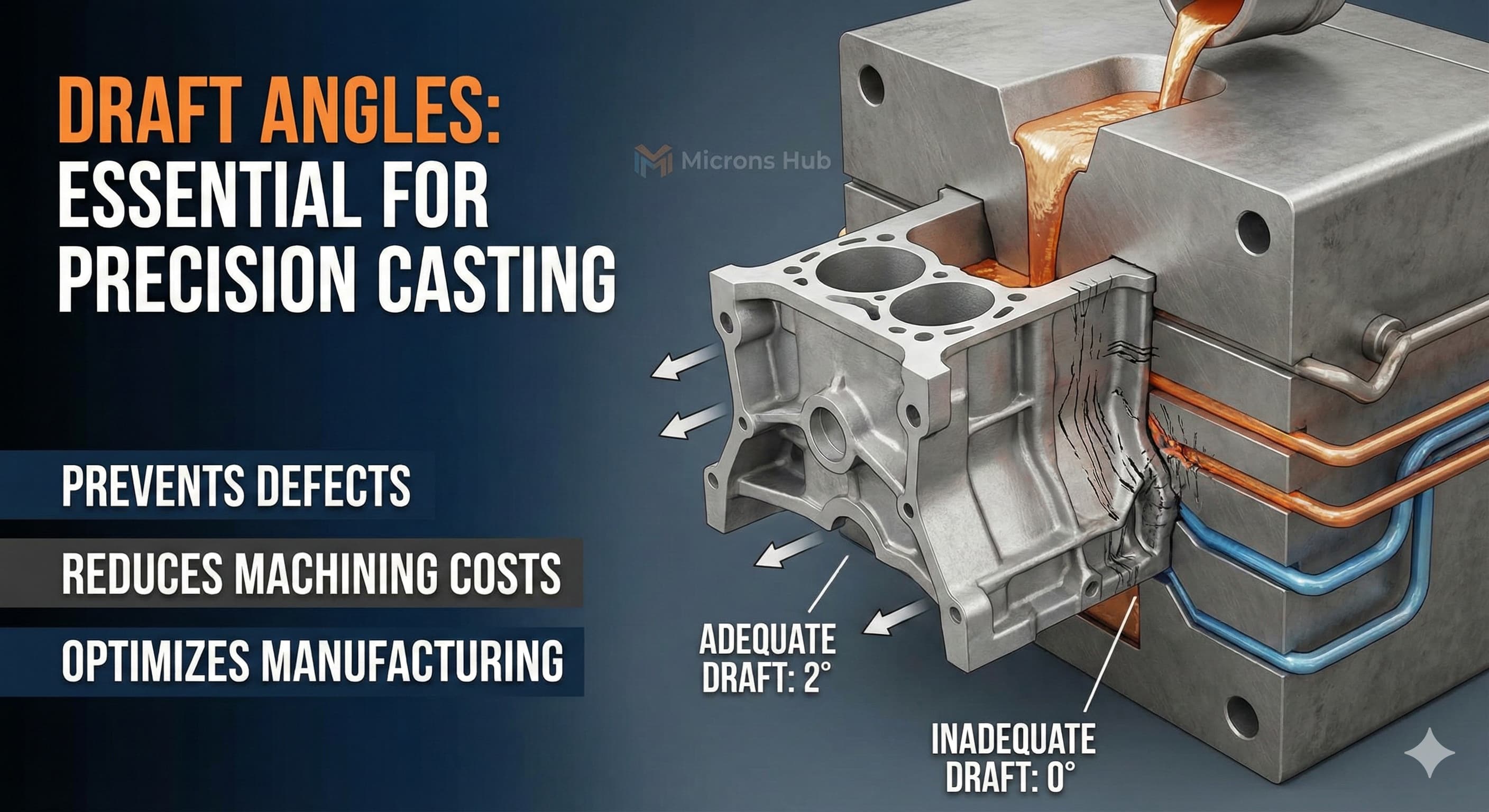
Draft angles are often overlooked during the design phase, yet inadequate draft specifications cause up to 40% of casting defects in precision metal components. The difference between a part that releases cleanly from the mold and one that requires expensive secondary operations lies in understanding the complex relationship between material properties, geometry, and manufacturing constraints.
Key Takeaways
- Draft angles typically range from 0.5° to 3° depending on casting process, with die casting requiring minimal angles (0.5-1°) while sand casting needs 1-3°
- Internal features require 25-50% steeper draft angles than external surfaces due to shrinkage forces during cooling
- Proper draft angle design can reduce machining costs by 30-60% by eliminating secondary operations on non-critical surfaces
- Material selection directly impacts draft requirements, with aluminum alloys allowing tighter angles than steel or iron castings
Understanding Draft Angle Fundamentals
Draft angles serve as the primary mechanism for successful part ejection from casting molds. Without adequate draft, the cooling metal shrinks onto the mold surfaces, creating interference that prevents clean separation. This fundamental shrinkage behavior varies significantly across different alloy systems and requires precise calculation for optimal results.
The physics behind draft requirements centers on thermal contraction coefficients. Aluminum alloys like A356-T6 exhibit linear shrinkage rates of approximately 1.3%, while ductile iron (ASTM A536) contracts at 1.0%. These differences directly translate to varying draft angle requirements, with aluminum castings often accommodating steeper angles due to lower shrinkage forces.
Manufacturing tolerances play a critical role in draft angle specification. Standard practice follows ISO 2768-m tolerances for medium precision castings, which typically allow ±0.5° variation in draft angles. However, high-precision applications may require tighter control at ±0.2°, necessitating more sophisticated tooling and process control measures.
Process-Specific Draft Angle Requirements
Die casting represents the most demanding application for draft angle optimization. The high-pressure injection process and rapid cooling cycles create unique challenges that require specific design considerations. Typical draft angles for die casting range from 0.5° to 1.5°, with the lower end reserved for external surfaces and simple geometries.
Sand casting processes allow for more generous draft angles due to the forgiving nature of sand molds. External surfaces typically require 1° to 2° draft, while internal features need 1.5° to 3°. The compressive strength of the sand mixture directly influences these requirements, with higher-strength molds allowing reduced draft angles.
Investment casting offers the tightest tolerances but requires careful draft consideration for wax pattern removal. Draft angles of 0.25° to 1° are common, with the ceramic shell process allowing for near-net-shape production. This precision comes at a cost premium of 20-40% compared to conventional sand casting methods.
| Casting Process | External Draft (°) | Internal Draft (°) | Typical Tolerance (±°) | Relative Cost |
|---|---|---|---|---|
| Die Casting | 0.5-1.5 | 0.75-2.0 | 0.2 | High |
| Sand Casting | 1.0-2.0 | 1.5-3.0 | 0.5 | Low |
| Investment Casting | 0.25-1.0 | 0.5-1.5 | 0.2 | Very High |
| Permanent Mold | 0.75-1.5 | 1.0-2.5 | 0.3 | Medium |
Material-Specific Draft Considerations
Aluminum alloys dominate precision casting applications due to their favorable shrinkage characteristics and excellent machinability. A356-T6, the most common aerospace casting alloy, allows draft angles as low as 0.5° for simple geometries. The T6 heat treatment provides dimensional stability that maintains draft angle integrity throughout the thermal cycling process.
Steel castings present greater challenges due to higher shrinkage forces and increased mold adhesion. Carbon steel grades like ASTM A216 WCB require minimum draft angles of 1.5° for external surfaces, increasing to 2.5° for internal features. The higher melting temperature and thermal expansion coefficient contribute to these increased requirements.
Cast iron applications, particularly ductile iron conforming to ASTM A536, exhibit moderate draft requirements between aluminum and steel. Grade 65-45-12 ductile iron typically requires 1° to 2° draft on external surfaces, with internal features needing 1.5° to 2.5°. The graphite structure provides some lubricity during ejection, reducing adhesion forces compared to steel.
| Material | Shrinkage Rate (%) | Min. External Draft (°) | Min. Internal Draft (°) | Machinability Rating |
|---|---|---|---|---|
| A356-T6 Aluminum | 1.3 | 0.5 | 0.75 | Excellent |
| A380 Aluminum | 1.2 | 0.5 | 0.75 | Good |
| ASTM A216 WCB Steel | 2.1 | 1.5 | 2.5 | Fair |
| A536 Ductile Iron | 1.0 | 1.0 | 1.5 | Good |
Geometric Complexity and Draft Optimization
Complex geometries require sophisticated draft angle strategies that account for varying wall thicknesses, undercuts, and transition zones. Deep cavities present particular challenges, as the increased surface contact area amplifies ejection forces. A general rule applies a 0.1° increase in draft angle for every 25 mm of cavity depth beyond the initial 50 mm.
Ribbing and boss features demand careful draft consideration to prevent stress concentration during ejection. Ribs should maintain consistent draft angles with the primary surfaces, while bosses require independent draft analysis. The intersection zones between features often become critical areas where inadequate draft leads to tearing or galling during part removal.
Multi-directional parting lines complicate draft angle implementation significantly. Each parting surface requires independent draft consideration, often resulting in compromise solutions that balance manufacturability with functional requirements. Advanced CAD systems now incorporate draft analysis tools that visualize potential ejection conflicts before tooling fabrication.
Surface Finish Impact on Draft Requirements
Surface finish specifications directly influence draft angle requirements through their effect on mold-to-part adhesion. Ra values below 3.2 μm increase surface contact area, requiring steeper draft angles to overcome adhesion forces. Conversely, controlled roughness patterns can reduce draft requirements by minimizing contact area.
Textured surfaces present unique challenges for draft angle calculation. Leather grain textures, commonly specified for aesthetic applications, can increase effective draft requirements by 0.25° to 0.5° depending on texture depth. The direction of texture application relative to the draft direction becomes critical for successful part ejection.
For high-precision results, Receive a detailed quote within 24 hours from Microns Hub.
EDM (Electrical Discharge Machining) surface finishes, while providing excellent dimensional accuracy, create micro-textures that can increase adhesion forces. Parts requiring EDM finishing often need 0.2° to 0.3° additional draft angle to compensate for the increased surface interaction. This consideration becomes particularly important for precision tooling applications where surface integrity is paramount.
Economic Optimization Through Draft Design
Draft angle optimization directly impacts manufacturing costs through its effect on secondary machining requirements. Parts designed with adequate draft can often eliminate machining operations on non-critical surfaces, reducing overall production costs by 30-60%. This cost reduction becomes more significant as production volumes increase.
Tooling costs correlate strongly with draft angle complexity. Simple, uniform draft angles minimize tooling complexity and reduce fabrication time. Complex draft requirements can increase tooling costs by 25-40% due to the additional machining time required for mold cavities. The trade-off between part functionality and manufacturing cost requires careful analysis during the design phase.
Secondary operations like CNC machining post-casting become necessary when draft angles cannot provide the required surface finish or dimensional accuracy. Strategic placement of these machined surfaces, combined with optimized draft angles on remaining surfaces, provides the most economical manufacturing approach.
When ordering from Microns Hub, you benefit from direct manufacturer relationships that ensure superior quality control and competitive pricing compared to marketplace platforms. Our technical expertise and personalized service approach means every project receives the attention to detail it deserves, with draft angle optimization included in our comprehensive design review process.
Advanced Draft Angle Techniques
Variable draft angles represent an advanced technique for optimizing complex geometries. This approach applies different draft angles to various sections of the same feature based on local geometry requirements. Deep pockets might start with 0.5° draft at the parting line, increasing to 2° at maximum depth to facilitate ejection.
Compound draft angles combine linear draft with curved transitions to accommodate complex surface geometries. Automotive applications frequently employ this technique for aesthetic components where straight draft lines would be visually objectionable. The calculation complexity increases significantly, requiring specialized CAD tools for accurate implementation.
Split-line draft management becomes critical in multi-cavity tooling where individual cavities may have different draft requirements. Balancing the draft angles across multiple cavities while maintaining consistent part quality requires sophisticated process control and tooling design. This complexity often justifies the additional engineering investment for high-volume production runs.
Quality Control and Draft Verification
Draft angle verification requires specialized measurement techniques beyond conventional dimensional inspection. Coordinate measuring machines (CMMs) equipped with rotary tables provide the most accurate draft angle measurement, typically achieving ±0.05° accuracy when properly calibrated. This precision becomes essential for high-volume production where small variations can accumulate into significant quality issues.
Optical measurement systems offer rapid draft angle verification for production environments. These non-contact systems can measure draft angles across entire part surfaces, identifying variations that might indicate tooling wear or process drift. Implementation of such systems typically reduces inspection time by 40-60% compared to traditional contact methods.
Statistical process control (SPC) applied to draft angle measurements provides early warning of tooling degradation. Tracking draft angle variations over time reveals patterns that predict when tooling maintenance or replacement becomes necessary. This proactive approach can prevent quality issues and reduce scrap rates significantly.
For applications requiring leak-tight assemblies, proper draft angles work in conjunction with vacuum impregnation processes to ensure optimal sealing performance. The surface integrity achieved through proper draft design enhances the effectiveness of subsequent sealing operations.
Integration with Modern Manufacturing
Digital manufacturing workflows now incorporate draft angle optimization as an automated design check. AI-powered design systems can analyze complex geometries and recommend optimal draft angles based on material selection, casting process, and quality requirements. These systems reduce design iteration time while improving manufacturability predictions.
Additive manufacturing of casting patterns allows for more complex draft angle implementations that would be difficult or impossible with traditional pattern-making techniques. 3D-printed patterns can incorporate variable draft angles and complex geometries while maintaining dimensional accuracy. This capability opens new possibilities for optimizing part design without traditional manufacturing constraints.
The integration of casting processes with complementary manufacturing methods like sheet metal fabrication services requires careful consideration of draft angles in hybrid assemblies. Components that will be welded or joined to cast parts need compatible draft angles to ensure proper fit and finish in the final assembly.
Industry 4.0 implementations track draft angle performance across entire product lifecycles, from design through production and field service. This comprehensive data collection enables continuous improvement in draft angle specifications and manufacturing processes. The resulting optimization can improve part quality while reducing manufacturing costs across our manufacturing services.
Frequently Asked Questions
What is the minimum draft angle for aluminum die castings?
Aluminum die castings typically require minimum draft angles of 0.5° for external surfaces and 0.75° for internal features. These values apply to standard A380 and A356 alloys with wall thicknesses above 2 mm. Thinner walls or complex geometries may require increased draft angles up to 1.5°.
How does surface finish affect draft angle requirements?
Surface finish directly impacts draft requirements through mold-to-part adhesion. Smoother surfaces (Ra< 3.2 μm) increase contact area and require steeper draft angles, typically adding 0.2-0.3° to standard requirements. Textured surfaces may need additional 0.25-0.5° depending on texture depth and direction.
Can draft angles be eliminated entirely through post-casting machining?
While machining can eliminate the need for draft angles on finished surfaces, the casting process still requires draft for successful mold release. Strategic design places machined surfaces on critical dimensions while maintaining adequate draft on remaining surfaces for cost-effective production.
What draft angles are required for investment casting processes?
Investment casting allows the smallest draft angles, typically 0.25-1.0° for external surfaces and 0.5-1.5° for internal features. The ceramic shell process and wax pattern removal enable these tight tolerances, making investment casting ideal for near-net-shape applications.
How do I calculate draft angles for deep cavities and pockets?
Deep cavities require increased draft angles to overcome higher ejection forces. Apply a 0.1° increase for every 25 mm of depth beyond the initial 50 mm. For example, a 100 mm deep pocket would require an additional 0.2° beyond the standard draft angle for that casting process.
Do different aluminum alloys require different draft angles?
Yes, aluminum alloy composition affects draft requirements through varying shrinkage rates and mold adhesion characteristics. A356-T6 allows minimum angles due to excellent dimensional stability, while higher silicon content alloys may require slightly increased draft angles due to different shrinkage behaviors.
What happens if draft angles are insufficient during production?
Insufficient draft angles cause casting defects including surface tearing, dimensional distortion, increased cycle times, and premature tooling wear. In severe cases, parts may be impossible to remove from molds without damage, resulting in 100% scrap rates until tooling modifications are completed.
MICRONS HUB DV Ε.Ε. · VAT: EL803129638 · GEMI: 190254227000 · Industrial Area, Street B, Number 4, 71601 Heraklion, Crete, Greece