Deburring Standards: Specifying Edge Conditions for Safe Handling
Sharp edges from machining, stamping, and cutting operations create safety hazards and functional problems that require systematic deburring approaches. Proper edge condition specification prevents workplace injuries, improves part performance, and ensures consistent manufacturing outcomes across production runs.
Key Takeaways
- Edge break specifications must align with material properties and intended application requirements
- Deburring standards vary significantly between industries, with aerospace requiring tighter tolerances than general fabrication
- Automated deburring processes offer superior consistency but manual methods provide better control for complex geometries
- Cost-effective deburring strategies balance safety requirements with production efficiency through proper process selection
Understanding Edge Break Fundamentals
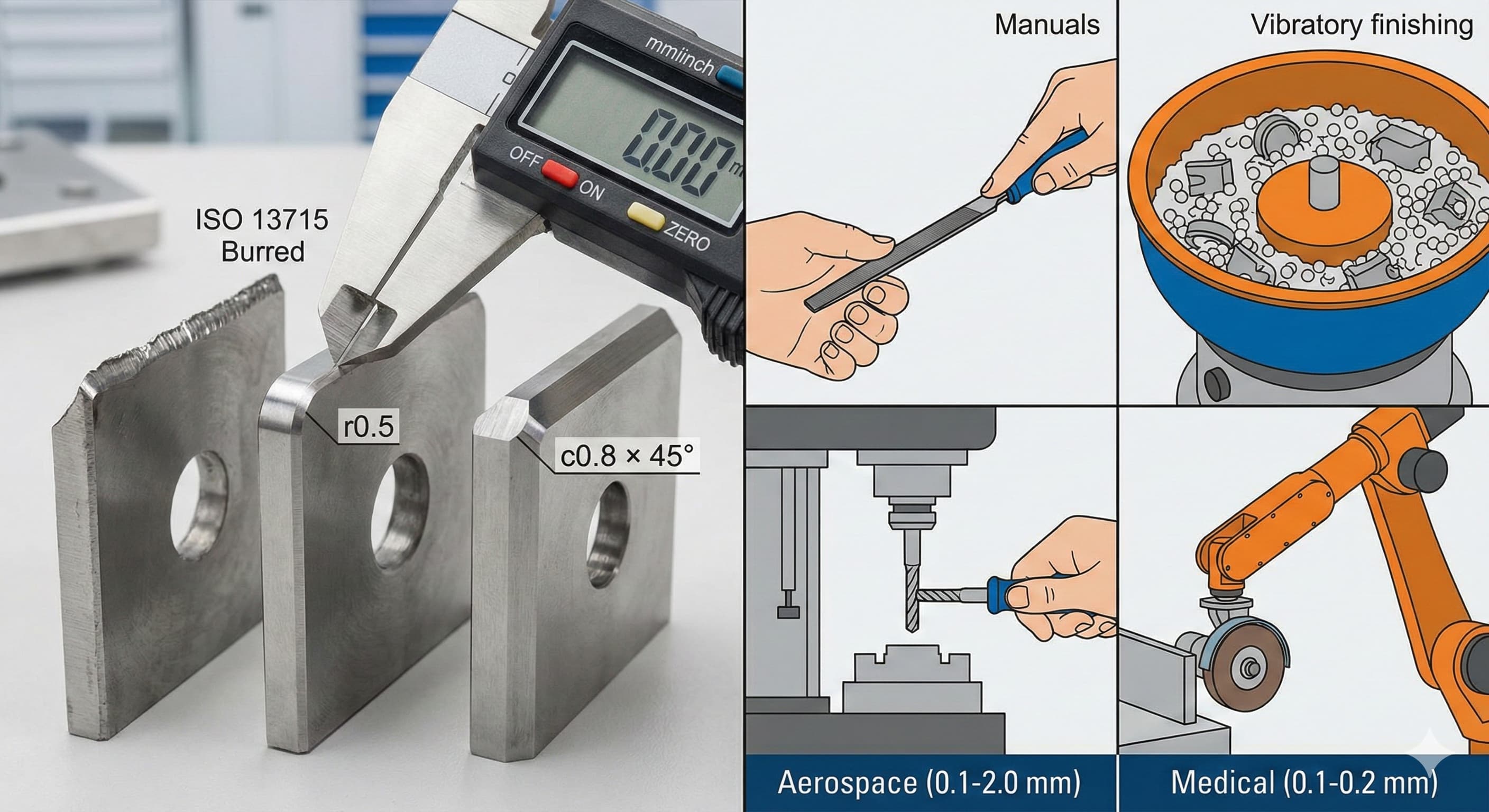
Edge break, defined as the intentional removal or modification of sharp edges, transforms potentially dangerous cutting surfaces into safe, functional edges. The fundamental measurement involves two key parameters: the edge radius and the chamfer dimension. Edge radius measurements typically range from 0.1 mm to 2.0 mm for most manufacturing applications, while chamfer specifications commonly fall between 0.2 mm and 1.5 mm at 45-degree angles.
Material properties directly influence edge break requirements. Aluminum alloys like 6061-T6 machine cleanly but produce sharp burrs that require consistent 0.2-0.4 mm edge breaks for safe handling. Stainless steel 316L generates more aggressive burrs during cutting operations, necessitating larger 0.5-0.8 mm edge breaks to eliminate all sharp projections. Carbon steel grades such as 1018 fall between these extremes, typically requiring 0.3-0.6 mm edge breaks depending on the cutting method used.
The geometry complexity significantly affects deburring approach selection. Simple rectangular parts with straight edges accommodate automated tumbling or vibratory finishing methods. Complex geometries with internal corners, holes, and varied thickness sections require selective manual deburring or specialized tooling approaches. Panel stiffeners with ribs and flanges exemplify this complexity, requiring careful attention to edge conditions where different material thicknesses meet.
Industry Standards and Specifications
ISO 13715 provides the foundational framework for specifying edge breaks on technical drawings, establishing standard notation and measurement methods. The standard defines edge break callouts using the format "r" for radius breaks and "c" for chamfer breaks, followed by the dimensional specification. For example, "r0.5" indicates a 0.5 mm radius break, while "c0.8 x 45°" specifies a 0.8 mm chamfer at 45 degrees.
| Industry | Typical Edge Break Range | Primary Standard | Critical Requirements |
|---|---|---|---|
| Aerospace | 0.1-2.0 mm | AS9100 | Stress concentration prevention |
| Medical Device | 0.1-0.2 mm | ISO 13485 | Biocompatibility and safety |
| Automotive | 0.2-1.0 mm | ISO/TS 16949 | Fatigue resistance |
| General Fabrication | 0.3-1.5 mm | ISO 9001 | Safe handling |
Aerospace applications follow AS9100 quality management standards that mandate specific edge break requirements for safety-critical components. Typical aerospace edge breaks range from 0.1-0.3 mm for precision parts up to 1.0-2.0 mm for structural components. These specifications ensure consistent performance under extreme operating conditions while maintaining precise dimensional tolerances.
Medical device manufacturing adheres to ISO 13485 standards that require burr-free surfaces for patient safety. Edge breaks in medical applications typically specify maximum 0.1-0.2 mm dimensions with smooth, consistent profiles. Sharp edges or remaining burrs can cause tissue damage or compromise device functionality, making rigorous deburring essential.
Deburring Process Selection
Manual deburring using files, scrapers, and abrasive tools provides maximum control for complex geometries and critical applications. Skilled operators can achieve consistent 0.1-0.5 mm edge breaks while preserving tight dimensional tolerances. Manual methods excel when dealing with varied part geometries, internal features, or when different edge break requirements exist on the same component. Labor costs typically range from €25-45 per hour depending on skill level and geographic location.
Tumbling processes utilize rotating drums filled with abrasive media to create uniform edge breaks across multiple parts simultaneously. Ceramic media produces aggressive cutting action suitable for 0.5-2.0 mm edge breaks, while plastic media provides gentler action for 0.2-0.8 mm breaks. Processing times range from 2-8 hours depending on material hardness and desired edge break size. Tumbling works effectively for parts without delicate features or tight tolerance requirements.
Vibratory finishing employs oscillating bowls or tubs containing abrasive media and parts in a carefully controlled environment. This method produces more consistent results than tumbling while maintaining better dimensional control. Vibratory systems can achieve edge breaks from 0.1-1.5 mm with processing times of 1-6 hours. Compound selection significantly affects results, with alkaline compounds promoting faster cutting and neutral compounds providing smoother finishes.
For high-precision results, Request a free quote and get pricing in 24 hours from Microns Hub.
Automated Deburring Technologies
CNC deburring systems integrate specialized tooling and programming to remove burrs during the primary machining operation. Chamfer mills, deburring tools, and brush systems can be programmed into machining cycles to create consistent edge breaks without secondary operations. This approach eliminates handling between operations while maintaining precise dimensional control. Typical edge breaks achievable through CNC deburring range from 0.1-1.0 mm with excellent repeatability.
Robotic deburring systems combine industrial robots with various deburring tools to automate complex edge break operations. Force-controlled robots can follow part contours while maintaining consistent pressure against cutting tools or abrasive wheels. Programming flexibility allows different edge break specifications on the same part, making robotic systems ideal for mixed production environments. Investment costs range from €150,000-500,000 depending on system complexity and tooling requirements.
| Deburring Method | Edge Break Range | Typical Cycle Time | Investment Cost |
|---|---|---|---|
| Manual | 0.1-0.5 mm | 5-30 min/part | €500-2,000 |
| Tumbling | 0.5-2.0 mm | 2-8 hours | €15,000-50,000 |
| Vibratory | 0.1-1.5 mm | 1-6 hours | €25,000-75,000 |
| CNC Integration | 0.1-1.0 mm | 1-5 min/part | €5,000-25,000 |
| Robotic | 0.2-2.0 mm | 2-15 min/part | €150,000-500,000 |
Thermal deburring, also known as explosion deburring, uses controlled combustion to remove burrs from internal passages and complex geometries. This process effectively reaches areas inaccessible to conventional deburring methods while creating consistent 0.1-0.3 mm edge breaks. Thermal deburring works particularly well for injection molding components with intricate internal features that require burr-free surfaces for proper function.
Material-Specific Deburring Considerations
Aluminum alloys require careful deburring approach selection due to their tendency to load cutting tools and generate stringy burrs. 6061-T6 aluminum responds well to sharp deburring tools with positive rake angles and adequate chip evacuation. Recommended cutting speeds range from 200-400 surface feet per minute with feed rates of 0.05-0.15 mm per revolution. Flood coolant prevents material buildup on cutting edges while maintaining dimensional stability.
Stainless steel grades like 316L and 304 present work hardening challenges that affect deburring tool selection. Carbide deburring tools maintain sharp cutting edges longer than high-speed steel alternatives when processing stainless materials. Cutting speeds should be reduced to 100-200 surface feet per minute to prevent excessive heat generation that can cause work hardening. Consistent feed rates prevent tool rubbing that leads to poor surface finishes and premature tool wear.
Carbon steel materials generally machine and deburr predictably across common grades like 1018, 1045, and 4140. Tool selection depends primarily on material hardness rather than work hardening characteristics. Annealed carbon steels accept aggressive deburring parameters, while hardened grades require more conservative approaches. Copper busbar fabrication demonstrates how material properties affect both primary processing and deburring requirements for electrical applications.
Quality Control and Measurement
Edge break measurement requires appropriate tooling and techniques to ensure specification compliance. Optical comparators provide non-contact measurement for edge radius and chamfer dimensions with accuracy to 0.01 mm. Radius gauges offer quick go/no-go verification for production environments where speed matters more than precision measurement. Contact profilometers deliver the highest accuracy for critical applications requiring documentation of actual edge break profiles.
Surface roughness specifications often accompany edge break requirements, particularly in aerospace and medical applications. Ra values from 0.8-3.2 μm are common for deburred edges, with smoother finishes required for applications involving human contact or fluid flow. Surface roughness measurement using portable roughness testers enables production floor verification without laboratory equipment.
Statistical process control implementation tracks deburring consistency across production runs and identifies trends before parts fall outside specification limits. Control charts monitoring edge break dimensions help optimize process parameters and reduce scrap rates. When ordering from Microns Hub, you benefit from direct manufacturer relationships that ensure superior quality control and competitive pricing compared to marketplace platforms. Our technical expertise and comprehensive measurement capabilities mean every project receives the attention to detail required for consistent edge break specifications.
Cost Optimization Strategies
Process consolidation reduces handling and setup costs by integrating deburring operations with primary manufacturing steps. CNC programming that includes deburring tool paths eliminates secondary operations while maintaining dimensional control. Part design modifications such as specifying uniform edge breaks across all edges simplify processing and reduce inspection requirements.
Batch processing maximizes equipment utilization for tumbling and vibratory finishing operations. Grouping parts with similar deburring requirements allows longer processing runs with consistent media and compound selection. Proper part fixturing prevents damage during automated deburring while ensuring uniform results across all surfaces.
Tool life optimization through proper selection and maintenance reduces per-part deburring costs. Carbide deburring tools justify higher initial costs through extended tool life in production environments. Regular tool inspection and replacement schedules prevent quality issues while maintaining consistent cycle times. Our manufacturing services include comprehensive tool management programs that optimize deburring operations for cost-effective production.
Safety and Handling Requirements
Personal protective equipment specifications for deburring operations must address both mechanical and chemical hazards. Cut-resistant gloves rated Level 3 or higher protect against sharp edges and rotating tools. Safety glasses with side shields prevent eye injuries from flying particles during manual deburring operations. Respiratory protection may be required when processing materials that generate harmful dust or when using chemical compounds in finishing operations.
Workstation design affects both safety and productivity in manual deburring operations. Proper lighting eliminates shadows that can hide remaining burrs or sharp edges. Ergonomic tool handles reduce hand fatigue during extended deburring sessions. Parts should be securely fixtured to prevent movement during deburring operations that could cause injuries or dimensional errors.
Automated system safety features include light curtains, emergency stops, and proper guarding around rotating equipment. Lockout/tagout procedures ensure safe maintenance access to tumbling and vibratory equipment. Material handling systems should minimize manual lifting and positioning of heavy parts during deburring operations.
Frequently Asked Questions
What edge break specification should I use for general fabrication work?
For general fabrication applications, edge breaks of 0.3-0.6 mm provide adequate safety for handling while remaining cost-effective. Specify uniform edge breaks across all part edges when possible to simplify processing. Consider material thickness and intended application when determining specific dimensions.
How do I specify edge breaks on technical drawings?
Use ISO 13715 notation with "r" for radius breaks and "c" for chamfer breaks followed by the dimension. For example, "r0.5" indicates a 0.5 mm radius break. Include general notes for uniform edge breaks or dimension specific edges individually when requirements vary.
Can deburring affect part dimensions and tolerances?
Yes, aggressive deburring can remove material beyond the intended edge break, affecting critical dimensions. Specify edge break locations carefully and consider dimensional stack-up effects. CNC deburring typically provides the best dimensional control for precision parts.
What deburring method works best for small batch production?
Manual deburring offers the most flexibility for small batches with varied geometries. Vibratory finishing works well for small batches of similar parts that require uniform edge breaks. Consider setup costs versus labor costs when selecting methods for small quantities.
How do I control deburring quality in automated systems?
Implement regular measurement checks using go/no-go gauges or optical measurement systems. Monitor process parameters like media condition, cycle times, and part positioning. Establish control charts to track edge break consistency and identify trends before quality issues occur.
What safety considerations apply to deburring operations?
Always wear appropriate PPE including cut-resistant gloves and safety glasses. Ensure proper ventilation when using chemical compounds or processing materials that generate harmful particles. Implement proper lockout/tagout procedures for automated equipment maintenance.
How does material hardness affect deburring requirements?
Harder materials typically require more aggressive deburring methods and longer processing times. Tool selection becomes critical for hardened materials to prevent premature wear. Consider annealing before deburring when processing very hard materials, then heat treating to final hardness if required.
MICRONS HUB DV Ε.Ε. · VAT: EL803129638 · GEMI: 190254227000 · Industrial Area, Street B, Number 4, 71601 Heraklion, Crete, Greece