Chamfers vs. Fillets: Which Edge Break Method is Cheaper to Machine?
Manufacturing engineers face a critical cost decision on every machined part: should edge breaks be chamfers or fillets? This seemingly minor detail can swing production costs by 15-40% depending on part geometry, material selection, and production volume. The choice impacts not only machining time but also tool wear, surface finish quality, and downstream assembly processes.
Most engineers default to chamfers for their apparent simplicity, but this assumption often leads to suboptimal cost outcomes. The reality involves complex interactions between cutting tool geometry, spindle speeds, material removal rates, and toolpath efficiency that demand deeper analysis.
- Chamfers typically reduce machining time by 25-35% compared to fillets in standard CNC operations
- Fillet radii below 0.5 mm require specialized tooling that increases costs by €0.15-€0.45 per linear meter
- Material hardness above 45 HRC significantly favors chamfer geometry for tool life optimization
- Production volumes above 500 units often justify fillet tooling investments despite higher setup costs
Understanding Edge Break Fundamentals
Edge breaks serve multiple engineering functions beyond aesthetics. Sharp edges create stress concentrations that can initiate fatigue cracks, particularly in cyclic loading applications. They also present safety hazards during handling and assembly operations. From a manufacturing perspective, controlled edge breaks eliminate the microscopic burrs and sharp projections that inevitably result from machining operations.
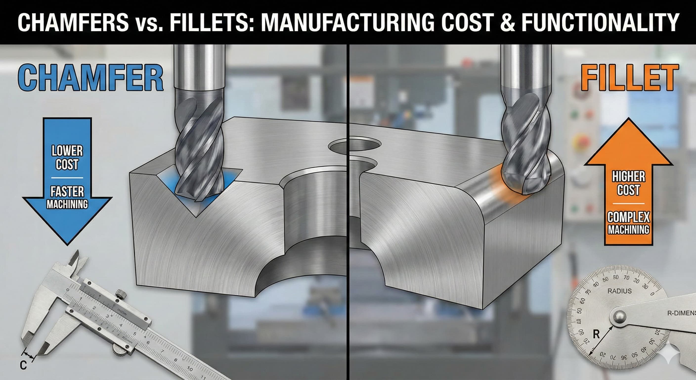
Chamfers represent the simplest geometric solution—a straight angular cut that removes the sharp edge intersection. Standard chamfer angles range from 30° to 60°, with 45° being most common due to tooling availability and ease of inspection. Chamfer dimensions typically follow the notation "C0.5" indicating a 0.5 mm chamfer at 45°, though other angles require specific callouts like "0.5 x 30°".
Fillets create a smooth radius transition between surfaces, eliminating the angular intersection entirely. Common fillet radii range from R0.2 mm for fine features up to R5.0 mm or larger for structural applications. Unlike chamfers, fillets provide superior stress distribution and fatigue resistance, making them preferred for highly loaded components.
The manufacturing implications differ significantly between these approaches. Chamfers can often be created using standard end mills or chamfer tools in a single pass, while fillets require ball end mills or radius tools with carefully programmed toolpaths to maintain consistent surface finish.
Machining Process Analysis
Chamfer machining leverages straightforward cutting mechanics. Standard chamfer tools feature single-point cutting edges ground to precise angles, allowing full-width cuts in a single pass. This approach minimizes spindle time and reduces programming complexity. Tool engagement remains consistent throughout the cut, enabling predictable cutting forces and excellent surface finish.
For chamfers up to 2.0 mm on materials like aluminum 6061-T6, typical cutting parameters include:
| Parameter | Value Range | Optimization Notes |
|---|---|---|
| Spindle Speed | 8,000-15,000 RPM | Higher speeds for smaller chamfers |
| Feed Rate | 1,500-4,000 mm/min | Adjust based on material hardness |
| Depth of Cut | Full width single pass | Eliminates multiple passes |
| Tool Life | 15-25 linear meters | Carbide tools in aluminum |
Fillet machining presents greater complexity due to the curved geometry requirements. Ball end mills must follow precise 3D toolpaths to maintain consistent radius dimensions. Surface finish quality depends heavily on stepover distance—tighter spacing improves finish but increases machining time exponentially.
Critical fillet machining considerations include tool deflection, which becomes problematic with small radius tools. A 2.0 mm ball end mill extending 15 mm from the spindle can deflect 0.02-0.05 mm under normal cutting loads, directly affecting radius accuracy. This necessitates shorter, more rigid tooling or reduced cutting parameters.
Our precision CNC machining services utilize specialized fixtures and shortened tool holders to minimize deflection issues while maintaining optimal cutting parameters for both chamfer and fillet operations.
Cost Driver Analysis
Tool acquisition costs show immediate differences between chamfer and fillet operations. Standard chamfer tools range from €45-85 per tool for quality carbide options, with each tool capable of processing 15-25 linear meters in aluminum or 8-12 meters in steel. Specialized fillet tooling costs €65-150 per tool, depending on radius size and coating specifications.
The tool inventory impact compounds these costs. Chamfer tools cover wide dimensional ranges—a single 45° chamfer tool can create any chamfer size limited only by tool diameter. Fillet operations require dedicated tools for each radius size, multiplying inventory requirements. A typical job shop maintains 3-4 chamfer tools versus 12-18 radius tools for equivalent capability coverage.
Machining time differences prove even more significant than tooling costs in high-volume production. Chamfers typically require 0.8-1.2 minutes per linear meter of edge break, while fillets demand 2.5-4.5 minutes per linear meter due to the complex toolpath requirements and slower feed rates necessitated by ball end mill geometry.
| Operation | Setup Time | Cycle Time/Meter | Tool Cost | Tool Life |
|---|---|---|---|---|
| Chamfer (Standard) | 8-12 minutes | 0.8-1.2 minutes | €45-85 | 15-25 meters |
| Chamfer (Complex) | 12-18 minutes | 1.2-1.8 minutes | €65-120 | 12-18 meters |
| Fillet R0.5-2.0 | 15-25 minutes | 2.5-3.5 minutes | €85-140 | 8-15 meters |
| Fillet R2.0-5.0 | 12-20 minutes | 1.8-2.8 minutes | €95-150 | 12-22 meters |
Secondary operations also influence total cost equations. Chamfered edges often require light deburring to remove minor tool marks, adding €0.08-0.15 per linear meter in manual finishing costs. Well-executed fillet operations typically need no secondary finishing, though achieving this quality level demands precise machine setup and optimal cutting parameters.
Material-Specific Considerations
Material properties dramatically affect the cost equation between chamfers and fillets. In aluminum alloys like 6061-T6, both operations perform well with standard tooling and parameters. The material's excellent machinability and chip evacuation characteristics support aggressive cutting in either geometry.
Stainless steel grades like 316L present different challenges. The material's work-hardening tendency favors chamfer geometry, where consistent cutting engagement prevents the formation of hardened layers that can damage subsequent cuts. Fillet operations in stainless steel require careful attention to cutting speed and feed rate relationships to maintain proper chip formation and avoid work hardening in the curved transition zones.
High-strength steels above 40 HRC significantly favor chamfer operations. The linear cutting path allows for consistent tool engagement and predictable wear patterns. Fillet cutting in hardened materials often produces chatter due to varying cutting forces throughout the curved toolpath, leading to poor surface finish and accelerated tool wear.
For challenging materials, the approach selection can impact costs by 200-300%. In Inconel 718, chamfer operations might cost €2.50-3.20 per linear meter, while equivalent fillet operations could reach €7.50-9.80 per linear meter due to specialized tooling requirements and dramatically reduced cutting parameters.
When working with exotic materials or critical applications,specialized machining strategies become essential for maintaining both quality and cost-effectiveness.
For high-precision results,Get your custom quote delivered in 24 hours from Microns Hub.
Design for Manufacturing Optimization
Smart design choices can eliminate the chamfer versus fillet cost dilemma entirely. Strategic feature placement, dimensional standardization, and manufacturing-conscious geometry decisions reduce production costs regardless of edge break selection.
Standardizing on common chamfer sizes like C0.5, C1.0, and C1.5 allows maximum tool utilization across multiple projects. Similarly, fillet standardization around R0.5, R1.0, R2.0, and R3.0 reduces tooling inventory and setup complexity. Parts designed around these standard dimensions benefit from optimized cutting parameters and established tool life data.
Feature accessibility significantly impacts machining efficiency. Chamfers on external edges require minimal tool clearance and can often be machined with standard tooling. Internal fillets demand consideration for tool access, clearance requirements, and potential interference with workholding fixtures.
The interaction between edge breaks and adjacent features creates additional cost considerations. Chamfers typically terminate cleanly at intersecting features, while fillets may require complex blending geometry that increases programming time and machining complexity. These intersections should be carefully considered during the design phase to avoid costly surprises during production.
Tolerance specifications also affect cost relationships. Chamfers can typically be held to ±0.1 mm without special consideration, while fillet radius tolerances below ±0.05 mm may require specialized measurement equipment and tighter process control, adding €0.25-0.45 per feature to inspection costs.
Volume Production Economics
Production volume fundamentally alters the cost equation between chamfer and fillet operations. Low-volume prototyping and custom work heavily favors chamfers due to reduced setup complexity and tooling requirements. The time investment in fillet programming and specialized tooling setup cannot be amortized across sufficient parts to justify the additional complexity.
At moderate volumes (50-500 parts), the decision point shifts based on part-specific factors. Complex geometries with multiple radius requirements may justify dedicated tooling investments, while simple parts with minimal edge break requirements continue to favor chamfer approaches.
High-volume production above 1,000 parts opens additional optimization possibilities. Dedicated fixtures, specialized tooling, and optimized programs can reduce per-part fillet costs below chamfer alternatives in specific applications. The key lies in comprehensive analysis of all cost factors, including secondary operations, quality requirements, and downstream assembly considerations.
Automated production systems show particular affinity for chamfer operations due to their predictable cutting forces and simplified toolpath requirements. Lights-out manufacturing scenarios benefit from the reduced complexity and improved reliability of chamfer processes.
| Volume Range | Chamfer Cost/Part | Fillet Cost/Part | Recommended Approach |
|---|---|---|---|
| 1-25 parts | €0.85-1.20 | €1.85-3.20 | Chamfer preferred |
| 25-100 parts | €0.65-0.95 | €1.25-2.10 | Chamfer typically better |
| 100-500 parts | €0.45-0.75 | €0.85-1.45 | Depends on complexity |
| 500-2000 parts | €0.35-0.55 | €0.55-0.95 | Fillet competitive |
| 2000+ parts | €0.25-0.45 | €0.35-0.65 | Full analysis required |
When ordering from Microns Hub, you benefit from direct manufacturer relationships that ensure superior quality control and competitive pricing compared to marketplace platforms. Our technical expertise and personalized service approach means every project receives the attention to detail it deserves, whether optimizing for chamfer or fillet operations.
Quality and Inspection Considerations
Quality control requirements significantly influence the true cost of chamfer versus fillet operations. Chamfer inspection utilizes straightforward measurement techniques—basic calipers, height gauges, or optical comparators can verify dimensions quickly and accurately. Standard chamfer callouts like "C1.0" provide clear, unambiguous inspection criteria that minimize quality disputes and rework.
Fillet inspection demands more sophisticated approaches. Radius gauges provide basic verification for larger fillets, but precision measurement requires coordinate measuring machines (CMM) or specialized optical equipment. The curved geometry makes it difficult to establish clear measurement datums, potentially leading to interpretation differences between supplier and customer quality standards.
Surface finish requirements also differ between the two approaches. Chamfers typically achieve Ra 1.6-3.2 μm directly from machining operations, suitable for most applications without secondary finishing. Fillets require more careful attention to cutting parameters and toolpath strategies to achieve equivalent surface quality, particularly in the transition zones where tool engagement varies continuously.
For applications requiring superior surface finish (Ra 0.8 μm or better), fillets may actually provide cost advantages. The smooth curved transition eliminates the angular intersection that can collect contaminants or create cleaning difficulties in food-grade or pharmaceutical applications.
Documentation and traceability requirements favor chamfer operations due to their straightforward measurement and recording procedures. Quality certificates can clearly state "C1.0 ±0.1" with confidence, while fillet documentation may require more complex geometric dimensioning and tolerancing (GD&T) callouts to adequately define acceptance criteria.
Application-Specific Recommendations
Structural applications demanding maximum fatigue resistance clearly favor fillet geometry despite higher manufacturing costs. The smooth stress transition provided by properly designed fillets can extend component life by 200-400% compared to equivalent chamfered designs. In aerospace, automotive, or medical device applications where failure consequences are severe, the additional manufacturing investment proves justified.
Conversely, consumer products, enclosures, and general industrial components often perform adequately with chamfered edges at significantly reduced manufacturing costs. The key lies in matching edge break selection to actual performance requirements rather than defaulting to either approach without analysis.
Aesthetic considerations may override pure cost optimization in visible components. Fillets generally provide a more refined, finished appearance that consumers associate with higher quality. This perception value may justify additional manufacturing costs in consumer-facing applications.
Assembly and handling requirements also influence optimal selection. Chamfers provide consistent, predictable geometry that simplifies automated assembly processes and reduces the risk of interference or binding during part mating. Fillets, while smoother, can create ambiguous contact conditions that complicate automated assembly systems.
The relationship between edge breaks and other manufacturing processes like drilling operations should be considered during design optimization to ensure overall manufacturing efficiency.
Our comprehensive approach through our manufacturing services ensures that edge break selection aligns with your specific application requirements while optimizing overall production costs.
Future Technology Trends
Emerging manufacturing technologies are reshaping the cost dynamics between chamfer and fillet operations. Advanced CAM software with automated toolpath optimization reduces the programming complexity traditionally associated with fillet operations. Machine learning algorithms can now optimize cutting parameters in real-time, reducing the expertise gap between chamfer and fillet machining.
High-speed machining centers with improved spindle dynamics and vibration control are making small-radius fillet operations more economically viable. Tool manufacturers are developing specialized coatings and geometries that extend tool life in difficult fillet applications, gradually closing the cost gap with chamfer operations.
Hybrid manufacturing approaches combining additive and subtractive processes may eventually eliminate the chamfer versus fillet decision entirely. Parts could be printed with integrated fillet geometry and finish-machined for critical surfaces, capturing the benefits of both approaches.
Industry 4.0 implementation with real-time monitoring and predictive maintenance capabilities favors more complex operations like fillets by providing the process control necessary for consistent, repeatable results. Smart tooling with embedded sensors can optimize cutting parameters continuously, reducing the process knowledge gap that traditionally favored simpler chamfer operations.
Frequently Asked Questions
What is the typical cost difference between chamfer and fillet operations?
Chamfers typically cost 40-60% less than equivalent fillets in standard machining operations. For aluminum parts, chamfers average €0.45-0.75 per linear meter while fillets range from €0.85-1.45 per linear meter, including tooling, setup, and machining time. The exact difference depends on material, geometry complexity, and production volume.
Can chamfers and fillets be used interchangeably from a functional perspective?
Not always. While both eliminate sharp edges, fillets provide superior stress distribution and fatigue resistance due to their smooth radius transitions. Chamfers are adequate for general deburring and safety requirements but cannot match fillet performance in high-stress applications. Structural components under cyclic loading typically require fillet geometry regardless of cost implications.
What radius sizes make fillet operations cost-competitive with chamfers?
Larger fillet radii (R2.0 mm and above) approach chamfer cost-effectiveness due to more aggressive cutting parameters and improved tool life. Small radii below R0.8 mm require specialized tooling and conservative cutting parameters that significantly increase costs. The crossover point typically occurs around R1.5-2.0 mm depending on material and production volume.
How do material properties affect the chamfer versus fillet cost equation?
Hard materials above 45 HRC strongly favor chamfer operations due to consistent tool engagement and predictable wear patterns. Soft, gummy materials like pure aluminum may actually favor fillet operations because the continuous cutting action prevents built-up edge formation. Stainless steels and work-hardening alloys generally machine more economically with chamfer geometry due to their sensitivity to interrupted cuts.
What design features can minimize edge break machining costs regardless of geometry choice?
Standardizing on common sizes (C0.5, C1.0, R0.5, R1.0) maximizes tool utilization and reduces setup time. Ensuring adequate tool access and clearance eliminates the need for specialized fixtures or extended tooling. Avoiding complex intersections and blends reduces programming complexity and machining time for both chamfer and fillet operations.
How does production volume affect the optimal edge break selection?
Low volumes below 100 parts heavily favor chamfers due to reduced setup and tooling costs. Medium volumes of 100-1000 parts create a decision point where part complexity and performance requirements determine optimal selection. High volumes above 1000 parts can justify fillet tooling investments when functional requirements demand radius geometry, potentially achieving per-part costs competitive with chamfer operations.
What inspection and quality control differences exist between chamfers and fillets?
Chamfers use simple measurement tools like calipers and height gauges with clear dimensional callouts. Fillets require more sophisticated measurement equipment such as radius gauges or CMM systems for accurate verification. This difference adds €0.15-0.35 per feature to inspection costs for fillet geometry, particularly important in high-precision or certified applications requiring full dimensional reports.
MICRONS HUB DV Ε.Ε. · VAT: EL803129638 · GEMI: 190254227000 · Industrial Area, Street B, Number 4, 71601 Heraklion, Crete, Greece