Live Tooling Lathes: Combining Turning and Milling for Complex Geometries
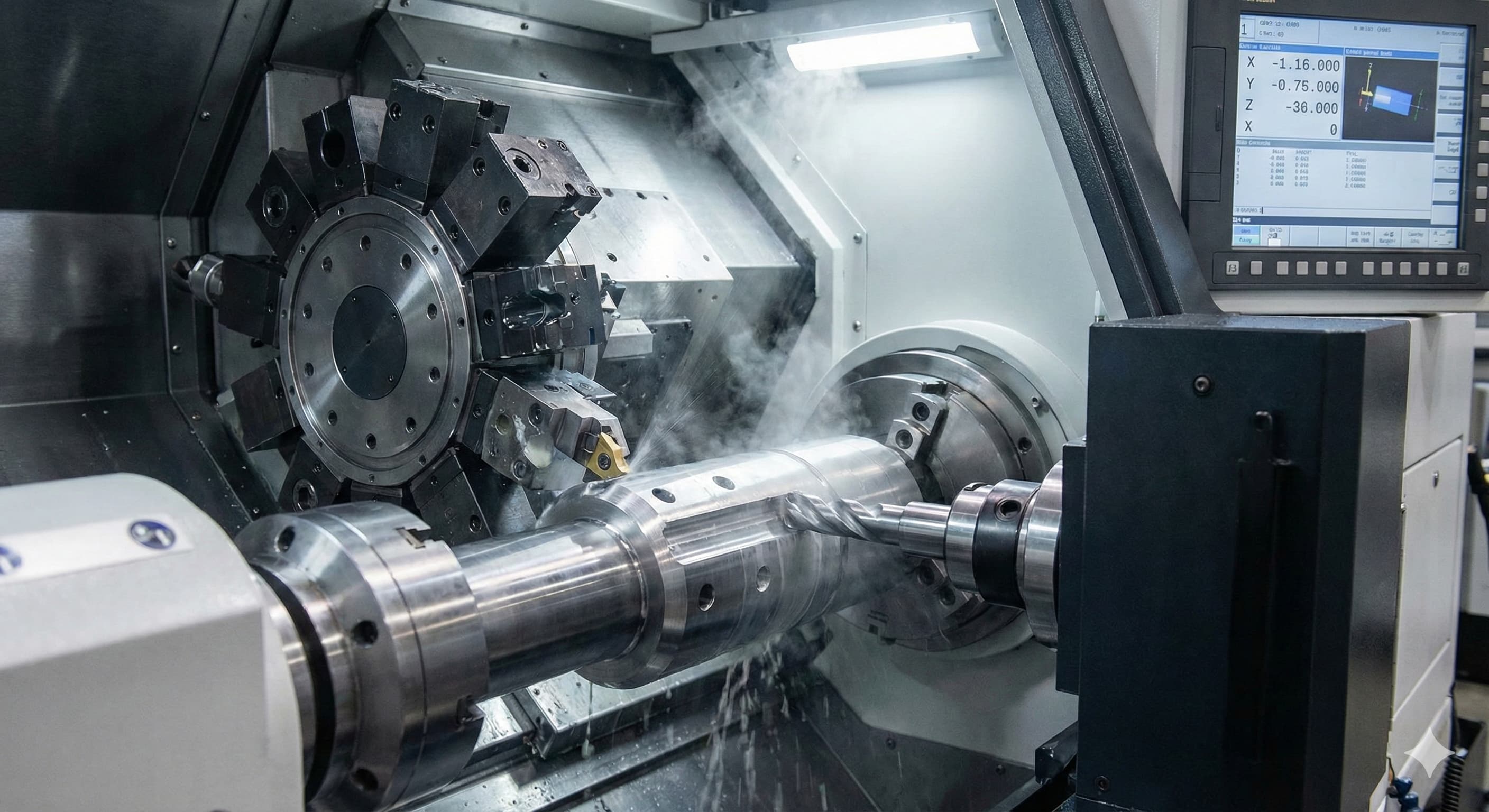
Live tooling lathes eliminate the traditional limitation of separating turning and milling operations by integrating powered cutting tools directly into the lathe spindle system. This technology enables manufacturers to complete complex geometries requiring both rotational and linear cutting motions in a single setup, reducing handling errors and dramatically improving part accuracy for components with tight tolerances below ±0.02 mm.
- Live tooling systems combine turning and milling capabilities in one setup, reducing part handling and improving accuracy for complex geometries
- Proper tool selection and spindle speed coordination between main and sub-spindles is critical for achieving surface finishes below Ra 0.8 μm
- Cost-effectiveness increases significantly for parts requiring both radial drilling, cross-milling, and turning operations compared to separate machine setups
- Integration challenges include thermal management, vibration control, and coordinated programming between multiple cutting axes
Understanding Live Tooling Technology Architecture
Live tooling systems integrate powered cutting tools directly into the lathe turret through dedicated spindle drives. Unlike static tooling that relies solely on workpiece rotation, live tools receive independent rotational power from electric or hydraulic motors mounted within the turret assembly. This dual-motion capability enables operations such as radial drilling, cross-milling, and complex contouring while the workpiece remains chucked in the main spindle.
The fundamental architecture consists of three primary components: the main spindle system handling workpiece rotation, the turret-mounted live tool spindles providing cutting tool rotation, and the coordinated CNC control system managing simultaneous multi-axis movements. Modern live tooling lathes typically feature 8-12 live tool positions with spindle speeds ranging from 50-6,000 RPM, depending on the specific tooling requirements and workpiece material.
Power transmission to live tools occurs through either direct-drive electric motors or hydraulic systems. Electric drive systems offer superior speed control precision and are preferred for applications requiring consistent surface finishes below Ra 1.6 μm. Hydraulic systems provide higher torque output, making them suitable for heavy-duty milling operations on materials like hardened steel or titanium alloys where cutting forces exceed 2,000 N.
The integration of live tooling significantly impacts machining vibration characteristics, particularly when cutting thin-walled sections where wall thickness falls below 3 mm. Proper system rigidity becomes critical to maintain dimensional accuracy across multiple cutting operations.
Operational Capabilities and Process Integration
Live tooling lathes excel in manufacturing components that traditionally required multiple setups across different machine types. The primary operational capabilities include radial drilling, off-center milling, gear cutting, polygon machining, and complex surface contouring. Each operation type requires specific consideration of cutting parameters, tool geometry, and workpiece fixturing to achieve optimal results.
Radial drilling operations benefit significantly from live tooling implementation, as holes can be machined perpendicular to the main axis without repositioning the workpiece. This capability proves essential for components like hydraulic manifolds, where precise hole positioning tolerances of ±0.05 mm must be maintained across multiple drilling operations. The elimination of setup changes reduces cumulative positional errors that typically accumulate during traditional multi-machine processing.
Cross-milling operations enable the creation of keyways, flats, and complex profiles along the workpiece length. The combination of workpiece rotation and live tool motion allows for helical milling, which produces superior surface finishes compared to conventional broaching or EDM processes. Helical interpolation techniques can achieve surface roughness values below Ra 0.4 μm on aluminum alloys like 6061-T6 when properly implemented.
Complex contouring operations represent the most advanced application of live tooling technology. By coordinating the main spindle C-axis with live tool rotation and linear movement, manufacturers can create intricate geometries such as cam profiles, irregular polygons, and sculptured surfaces. This capability proves particularly valuable for aerospace components and precision instrumentation parts where geometric complexity directly impacts functional performance.
Technical Specifications and Performance Parameters
Live tooling system performance depends heavily on spindle specifications, power transmission efficiency, and thermal management capabilities. Understanding these technical parameters enables proper system selection and optimal process planning for specific manufacturing requirements.
| Parameter | Standard Range | High-Performance Range | Application Impact |
|---|---|---|---|
| Live Tool Spindle Speed | 50-3,000 RPM | 100-8,000 RPM | Surface finish quality |
| Spindle Power | 3-7.5 kW | 7.5-22 kW | Material removal rates |
| Tool Holder Taper | BT30, BT40 | HSK-A63, HSK-E40 | Tool change speed, rigidity |
| Positioning Accuracy | ±0.01 mm | ±0.005 mm | Dimensional tolerance capability |
| Repeatability | ±0.005 mm | ±0.002 mm | Process consistency |
Spindle power requirements vary significantly based on material type and cutting parameters. Aluminum alloys typically require 2-5 kW for effective milling operations, while hardened steels and titanium alloys may demand 10-15 kW for comparable material removal rates. The power-to-weight ratio of the live tooling system directly impacts achievable cutting speeds and overall productivity.
Thermal management becomes critical during extended live tooling operations, particularly when cutting difficult-to-machine materials. Spindle temperature increases above 60°C can cause dimensional drift and premature tool wear. Advanced systems incorporate dedicated cooling circuits and temperature monitoring to maintain consistent performance throughout production runs.
Tool holder interface selection significantly impacts system rigidity and tool change efficiency. HSK systems provide superior clamping force and repeatability compared to traditional BT tapers, making them preferred for precision applications requiring tool change accuracy within ±0.003 mm.
Material Considerations and Cutting Strategies
Different materials require specific cutting strategies when processed on live tooling lathes. The combination of turning and milling operations creates unique challenges in terms of cutting forces, chip evacuation, and thermal generation that must be addressed through proper parameter selection and tooling design.
Aluminum alloys, particularly 6061-T6 and 7075-T6, respond well to live tooling operations due to their favorable machining characteristics. High spindle speeds between 2,000-4,000 RPM combined with aggressive feed rates up to 0.3 mm/rev enable excellent surface finishes and high material removal rates. The key challenge lies in chip management, as aluminum's tendency to form long, stringy chips can interfere with simultaneous turning and milling operations.
| Material | Recommended Speed (RPM) | Feed Rate (mm/rev) | Cooling Method | Primary Challenges |
|---|---|---|---|---|
| Al 6061-T6 | 2,000-4,000 | 0.2-0.4 | Flood coolant | Chip evacuation |
| Steel 1045 | 800-1,500 | 0.1-0.25 | High-pressure coolant | Heat generation |
| Stainless 316 | 400-800 | 0.05-0.15 | Through-tool cooling | Work hardening |
| Ti-6Al-4V | 200-500 | 0.05-0.1 | Cryogenic cooling | Tool wear, heat |
| Inconel 718 | 100-300 | 0.03-0.08 | High-volume flood | Rapid tool wear |
Steel materials present moderate challenges in live tooling applications. Carbon steels like AISI 1045 machine readily with proper cooling, while alloy steels require reduced cutting speeds to manage heat generation. The primary concern involves maintaining consistent cutting forces across both turning and milling operations to prevent workpiece deflection in thin-walled sections.
Stainless steel processing demands careful attention to work hardening prevention. The interrupted cutting nature of live tooling operations can cause surface hardening if cutting speeds drop below the minimum chip thickness threshold. Maintaining consistent feed rates above 0.05 mm/rev helps prevent this issue while ensuring acceptable tool life.
Titanium alloys represent the most challenging materials for live tooling applications. The low thermal conductivity of Ti-6Al-4V causes rapid heat buildup at cutting edges, leading to premature tool failure. Specialized cutting strategies involving trochoidal milling patterns and constant engagement angles help distribute heat load more effectively.
For high-precision results, Submit your project for a 24-hour quote from Microns Hub.
Tooling Selection and Setup Strategies
Proper tooling selection forms the foundation of successful live tooling operations. The unique requirements of simultaneous turning and milling demand specialized cutting tools designed to handle the dynamic cutting conditions and varying chip loads encountered during multi-axis machining.
End mill selection for live tooling applications differs significantly from conventional milling operations. Tools must withstand the centrifugal forces generated by workpiece rotation while maintaining cutting efficiency during radial engagement. Carbide tools with TiAlN coatings provide optimal performance for most applications, offering wear resistance and thermal stability up to 800°C cutting temperatures.
Tool geometry becomes critical when transitioning between turning and milling operations within the same program. Variable helix end mills reduce chatter potential during cross-milling operations, while unequal spacing helps minimize harmonic vibrations that can cause surface finish degradation. Corner radius selection must balance edge strength with achievable surface roughness requirements.
Drill selection for radial drilling operations requires consideration of both chip evacuation and hole quality requirements. Through-coolant drills prove essential for holes deeper than 3× diameter, as chip evacuation becomes difficult due to the compound motion of workpiece rotation and drill advance. Hole tolerance capabilities typically range from IT7 to IT9 depending on drill quality and setup rigidity.
Tool presetting accuracy directly impacts overall part quality and setup efficiency. Live tool systems require presetting tolerances within ±0.005 mm to maintain positional accuracy across multiple cutting operations. Advanced presetting equipment with automatic tool recognition systems reduces setup time while ensuring consistent tool positioning.
Programming and Process Optimization
CNC programming for live tooling lathes requires advanced techniques that coordinate multiple spindle systems while managing complex tool paths. Modern CAM software packages provide specialized modules for live tooling programming, but understanding the underlying principles remains essential for process optimization.
Synchronization between main spindle C-axis positioning and live tool operations requires precise timing control. The CNC system must coordinate workpiece angular position with tool engagement to ensure proper cutting geometry throughout the operation. This coordination becomes particularly critical during helical interpolation where angular and linear motions must remain perfectly synchronized to maintain constant chip load.
Feed rate optimization involves balancing productivity with surface finish requirements across different cutting operations. Turning operations typically achieve optimal results with constant surface speed programming, while milling operations benefit from constant feed per tooth strategies. The transition between these programming modes must occur seamlessly to prevent surface finish variations at operation boundaries.
Workpiece clamping strategies significantly impact achievable accuracy and surface finish quality. Traditional three-jaw chucks may introduce runout errors that become amplified during live tooling operations. Dedicated workholding fixtures designed for specific part geometries often provide superior results, particularly for components requiring concentricity tolerances below 0.02 mm.
Tool path optimization focuses on minimizing air cutting time while maintaining consistent cutting conditions. Rapid traverse movements between operations should follow optimized paths that avoid collision with both workpiece and fixture components. Advanced CAM systems provide simulation capabilities that verify tool paths and identify potential interference conditions before program execution.
Quality Control and Measurement Strategies
Quality control in live tooling operations requires comprehensive measurement strategies that address the unique challenges of multi-operation manufacturing. The combination of turning and milling features on a single part demands inspection techniques capable of verifying complex geometries with high accuracy and repeatability.
Coordinate measuring machines (CMMs) provide the most comprehensive solution for live tooling part inspection. The ability to measure both turned and milled features using consistent coordinate systems ensures proper feature relationships are maintained. Touch probe systems enable measurement of internal features that may be inaccessible with traditional gauging methods.
On-machine probing systems offer real-time verification capabilities that enable process adjustment during manufacturing. Modern live tooling lathes can be equipped with touch probes that verify critical dimensions immediately after machining, allowing for automatic offset adjustments to maintain tight tolerances throughout production runs.
Surface finish measurement becomes complex when dealing with parts containing both turned and milled surfaces. Different measurement techniques may be required for various surface orientations, and correlation between measurement methods must be established to ensure consistency. Turned surfaces typically exhibit circumferential lay patterns, while milled surfaces show directional patterns related to tool motion.
Statistical process control (SPC) implementation requires careful consideration of the multiple variables involved in live tooling operations. Control charts must account for tool wear progression across different cutting operations and the interaction effects between turning and milling processes on final part quality.
Cost Analysis and Economic Considerations
Live tooling implementation involves significant capital investment that must be justified through improved productivity, reduced setup costs, and enhanced part quality. Understanding the economic factors enables proper evaluation of live tooling systems for specific manufacturing applications.
Initial equipment costs for live tooling lathes range from €150,000 for basic systems to €800,000 for advanced multi-axis configurations. The cost premium over conventional lathes typically ranges from 40-70%, depending on the number of live tool positions and system complexity. This investment must be evaluated against the potential savings in setup time, labor costs, and improved quality consistency.
| Cost Factor | Conventional Process | Live Tooling Process | Savings Potential |
|---|---|---|---|
| Setup Time per Part | 45-60 minutes | 15-25 minutes | 50-65% |
| Handling Operations | 3-5 setups | 1 setup | 70-80% |
| Dimensional Accuracy | ±0.05 mm typical | ±0.02 mm achievable | Reduced scrap rates |
| Floor Space Requirements | Multiple machines | Single machine | 40-60% |
| Labor Requirements | 2-3 operators | 1 operator | 50-65% |
Tool costs represent a significant ongoing expense in live tooling operations. The specialized cutting tools required for live tooling applications typically cost 20-40% more than conventional tools due to their enhanced design requirements and lower production volumes. However, improved tool life resulting from better cutting conditions often offsets this initial cost premium.
Production volume considerations play a crucial role in economic justification. Live tooling systems demonstrate clear advantages for medium to high-volume production where setup time reduction provides substantial savings. For low-volume applications, the benefits may be less pronounced unless part complexity or quality requirements justify the investment.
When ordering from Microns Hub, you benefit from direct manufacturer relationships that ensure superior quality control and competitive pricing compared to marketplace platforms. Our technical expertise and personalized service approach means every project receives the attention to detail it deserves, particularly for complex live tooling applications requiring precise coordination between multiple manufacturing processes.
Many live tooling applications complement other manufacturing processes such as injection molding services where precision mold components require the complex geometries achievable through combined turning and milling operations. Our comprehensive manufacturing services enable seamless integration across multiple production technologies.
Implementation Challenges and Solutions
Successful live tooling implementation requires addressing several technical and operational challenges that can impact system performance and part quality. Understanding these challenges and their solutions enables more effective process planning and system optimization.
Thermal management represents one of the most significant challenges in live tooling operations. The combination of multiple cutting processes generates substantial heat that must be effectively removed to maintain dimensional stability. Inadequate cooling can cause thermal growth in both the workpiece and machine structure, leading to dimensional errors exceeding ±0.1 mm in critical features.
Vibration control becomes complex due to the interaction between multiple rotating systems. The main spindle, live tool spindles, and workpiece create a dynamic system prone to resonant frequencies that can cause chatter and surface finish degradation. Proper spindle speed selection and cutting parameter optimization help avoid problematic frequency ranges while maintaining productivity.
Chip management presents unique challenges when multiple cutting operations occur simultaneously or in rapid succession. Effective chip evacuation systems must handle the varying chip characteristics produced by different cutting operations while preventing chip interference with subsequent operations. High-pressure coolant systems and dedicated chip conveyor systems address these requirements.
Programming complexity increases significantly compared to conventional lathe operations. The coordination of multiple axes and tool systems requires advanced programming skills and comprehensive understanding of cutting mechanics. Investment in programmer training and advanced CAM software becomes essential for successful implementation.
Tool interference detection and collision avoidance require sophisticated programming and simulation capabilities. The proximity of multiple cutting tools and workholding devices creates numerous potential collision scenarios that must be identified and avoided through careful program verification and machine simulation.
Future Developments and Technology Trends
Live tooling technology continues evolving with advances in machine design, control systems, and cutting tool technology. Understanding these trends helps manufacturers make informed decisions about equipment investments and process development strategies.
Multi-tasking machine integration represents a significant trend where live tooling capabilities are combined with additional manufacturing processes such as grinding, gear cutting, and additive manufacturing. These hybrid systems enable complete part production in a single setup, further reducing handling requirements and improving overall productivity.
Artificial intelligence and machine learning integration enable predictive maintenance and automatic process optimization. Advanced control systems can monitor cutting conditions in real-time and adjust parameters automatically to maintain optimal performance while extending tool life and improving part quality consistency.
Tool monitoring systems using acoustic emission sensors and vibration analysis provide real-time feedback on cutting conditions and tool wear progression. These systems enable automatic tool change scheduling and process parameter adjustment to maintain consistent quality throughout production runs.
Advanced materials and coating technologies continue improving cutting tool performance for live tooling applications. Diamond-like carbon coatings and nanostructured tool surfaces provide enhanced wear resistance and reduced friction, enabling higher cutting speeds and extended tool life.
Frequently Asked Questions
What are the main advantages of live tooling lathes over separate turning and milling operations?
Live tooling lathes eliminate multiple setups by combining turning and milling in one operation, reducing handling errors and improving accuracy to ±0.02 mm. Setup time typically decreases by 50-65%, while dimensional consistency improves significantly due to single-point referencing throughout all cutting operations.
What types of parts benefit most from live tooling capabilities?
Components requiring radial drilling, keyways, flats, or complex profiles benefit most from live tooling. Examples include hydraulic manifolds, aerospace components, automotive transmission parts, and precision instrumentation components where geometric complexity and tight tolerances are critical.
How do cutting speeds and feeds differ between turning and milling operations on live tooling lathes?
Turning operations typically use surface speed programming (150-300 m/min for steel), while milling operations require spindle speed programming (500-3000 RPM). Feed rates must be coordinated between operations, with turning feeds of 0.1-0.4 mm/rev and milling feeds adjusted for chip load per tooth requirements.
What are the typical tolerance capabilities achievable with live tooling systems?
Modern live tooling lathes achieve positioning accuracy of ±0.005 mm and repeatability of ±0.002 mm. Dimensional tolerances of IT7-IT8 are routinely achievable, with IT6 possible under optimal conditions. Surface finish capabilities range from Ra 0.4-1.6 μm depending on material and cutting parameters.
How does tool wear progress differently in live tooling compared to conventional machining?
Live tooling applications often experience more uniform tool wear due to interrupted cutting conditions and better heat dissipation. However, tool selection becomes critical as tools must handle varying cutting forces and chip loads. Proper programming can extend tool life by 20-40% compared to conventional separate operations.
What cooling and lubrication strategies work best for live tooling operations?
High-pressure coolant systems (20-80 bar) provide optimal results for most live tooling applications. Through-tool cooling proves essential for drilling operations deeper than 3× diameter. Minimum quantity lubrication (MQL) systems offer environmental benefits while maintaining good surface finish quality for aluminum and steel materials.
How do programming requirements differ for live tooling compared to conventional CNC programming?
Live tooling programming requires coordination between main spindle C-axis and live tool motions, demanding advanced CAM software capabilities. Synchronization commands, tool interference checking, and multi-axis coordinate systems add complexity. Programming time typically increases 30-50% but setup time decreases significantly, resulting in overall time savings.
MICRONS HUB DV Ε.Ε. · VAT: EL803129638 · GEMI: 190254227000 · Industrial Area, Street B, Number 4, 71601 Heraklion, Crete, Greece